

In this article, we explore how an 8×8 LED Matrix Display works and how we can control it by creating software capable of displaying icons and simple animations using an Arduino.
The code is available on GitHub
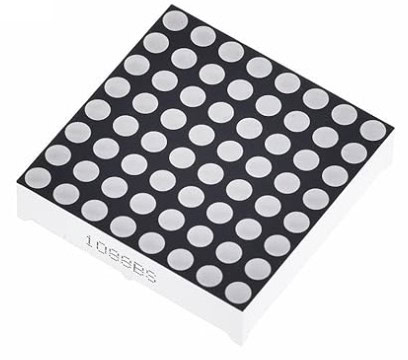
Parts Used
* This website includes affiliate product links. We may earn a commission if you make a purchase after clicking on one of these links. Your support is greatly appreciated!
How an 8×8 LED Display Works
An 8×8 LED Display consists of a grid of 64 LEDs arranged in rows and columns. To handle these numerous LEDs, a significant amount of wiring would be necessary. However, the component cleverly reduces the number of required pins through internal wiring, simplifying connections but complicating the software that controls the LED Display.
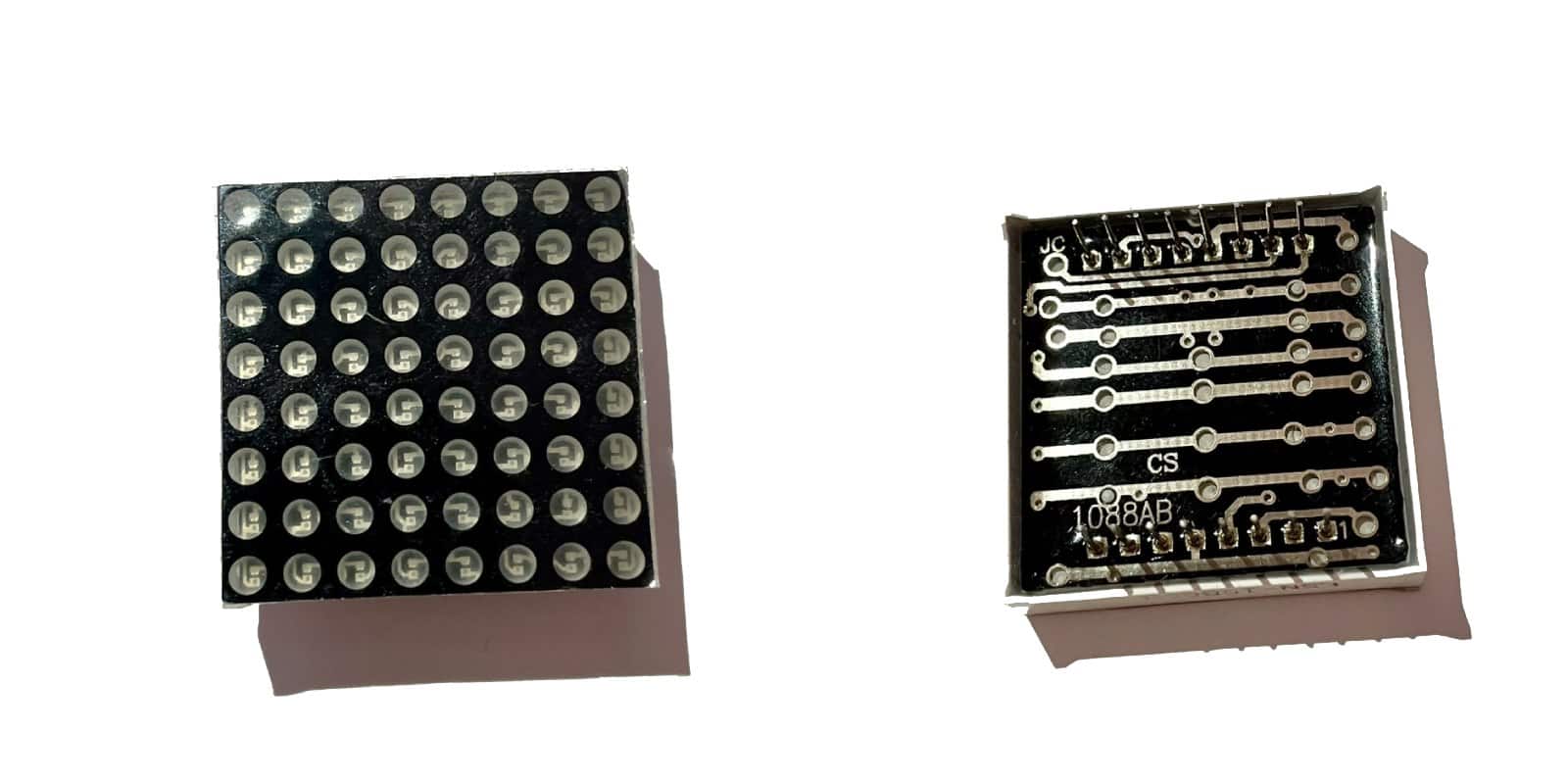
A standard 8×8 LED matrix Display has 16 pins, with 8 pins on each side of its back. The front and back of an 8×8 LED Display is shown below:
Each LED is a diode, with a cathode and an anode, that emits light. Internally, the cathodes of LEDs are connected within rows, while the anodes are connected within columns. This results in 8 pins for the row cathodes and another 8 for the column anodes. Alternatively, the setup can be reversed, interconnecting row anodes and column cathodes, leading to two types of LED displays: Row Common Cathode (where we connect together each cathode of LED in a row) and Column Common Cathode (where we connect each LED cathode of each column together).
The diagram below illustrates how the LEDs are internally connected, clarifying how we end up with 16 input pins of the LED Display component:
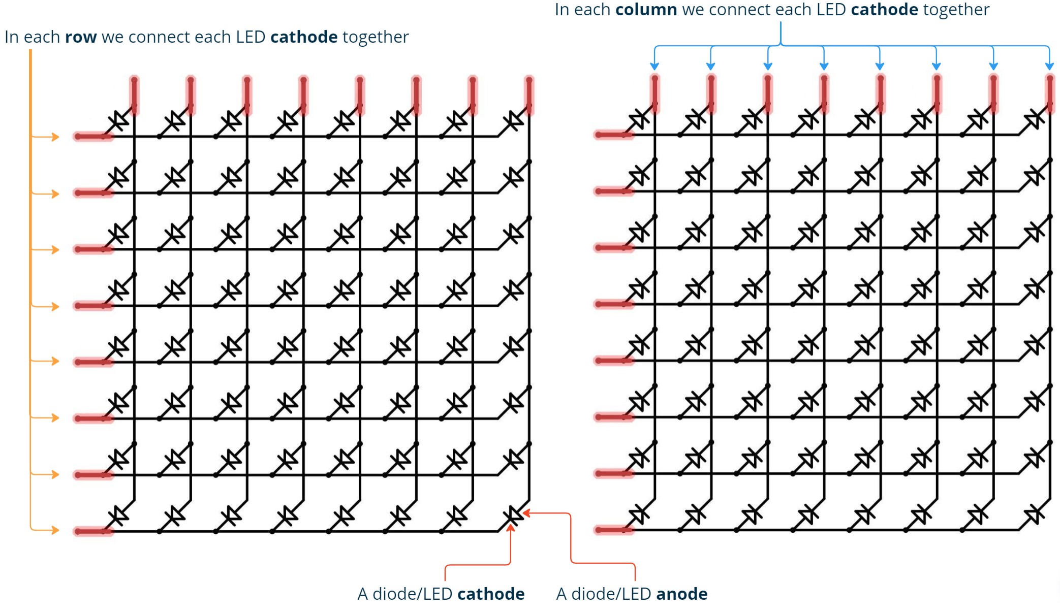
With this kind of internal connectivity, in order to light a particular LED we have to enable both its row and column. Depending on whether it’s a row common cathode or a column common cathode display, voltage should be applied to the corresponding row or column. For instance, to light the LED at the intersection of the 4th row and 4th column in a row cathode LED Display, we should apply 0V to the 4th row and 2V to its 4th column. This completes a current pathway, lighting the targeted LED.
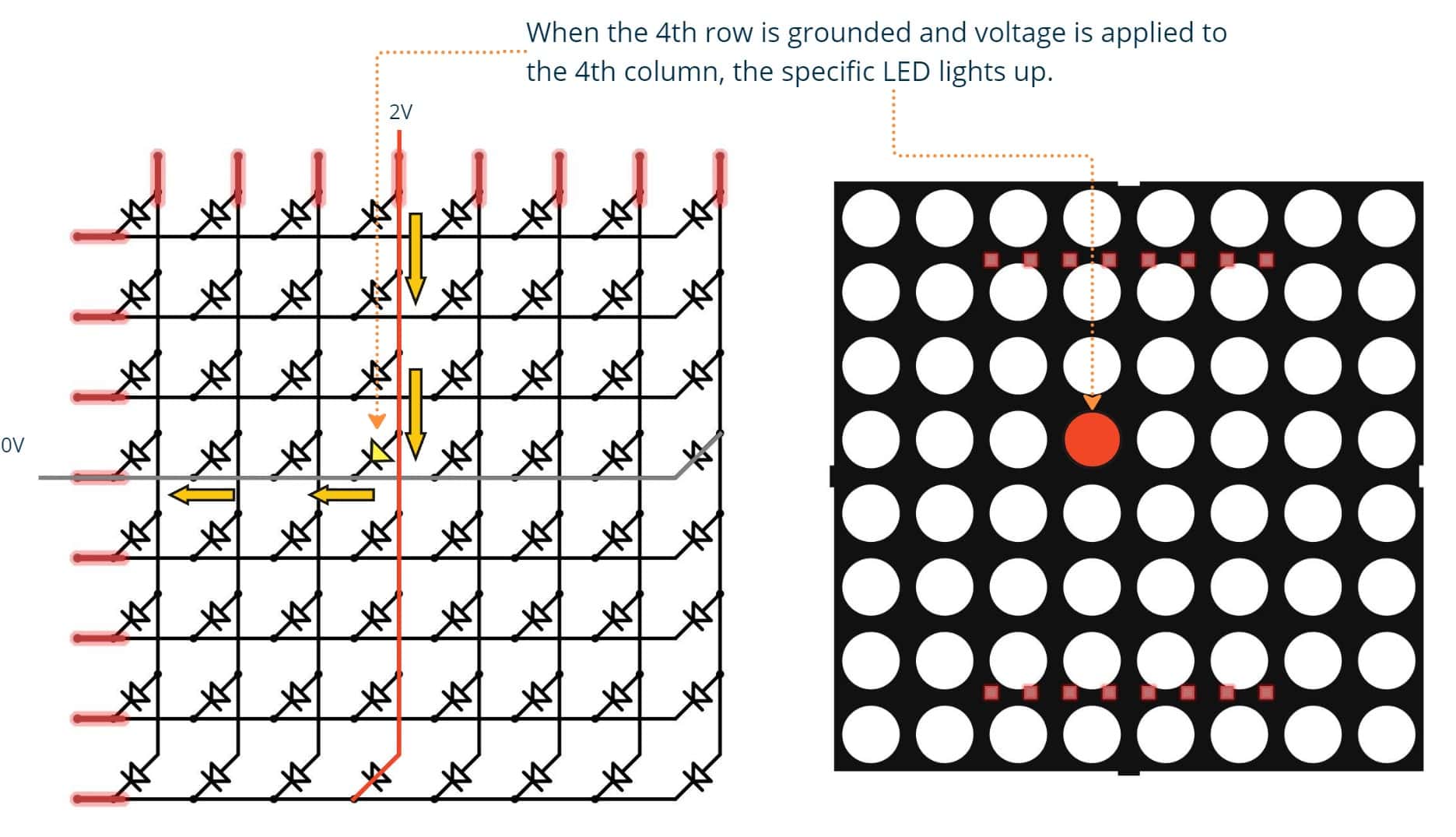
However, if we want to turn ON the LED of the 5th row and column, as with the previous one, we would normally have to ground the 5th row and apply voltage to the 5th column. However, this also activates the adjacent LEDs at positions (5,4) and (4,5). By grounding the 5th row and applying voltage to the 5th column, we unintentionally create additional pathways for the current, lighting two more LEDs. This issue can be resolved through a technique called Scanning, which we’ll examine in the next section.
Scanning
Scanning is a method for controlling a LED Display, enabling us to light up specific sections of the display at a given time. By controlling one row or one column at a time, we can display any image on the LED Display without accidentally activating LEDs that we don’t want to. However, this process needs to be fast enough to avoid noticeable transitions between rows or columns. This approach is also followed when controlling a 4-Digit 7-Segment Display, where we control certain segments of the Display at a time.
Learn How a 4-Digit 7-Segment LED Display Works and how to control it using an Arduino
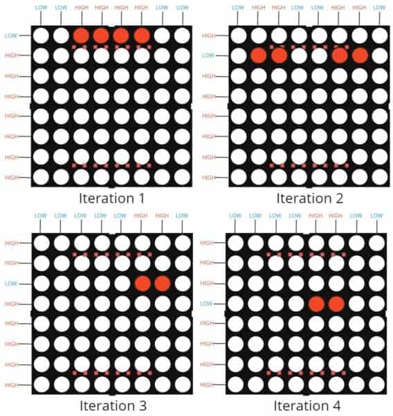
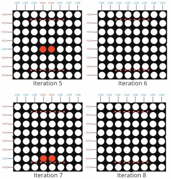
For an 8×8 LED Display Matrix, we perform scanning on either rows or columns. During each scan of a row or column, we set the corresponding LEDs in that row/column to their desired state, forming part of the entire image we aim to display. For instance, consider we want to display the following icon:
Suppose the Display is a Row-Cathode Column-Anode type, and we perform a row scanning in order to draw the icon. This means, for each row we scan, we set the current row to 0V (activating the row, because it’s a row cathode) and apply voltage to the columns where we want the LEDs to turn ON. This iteration will take place 8 times, as many as the rows.
Below we illustrate each iteration and the state of the rows and columns in order to display the corresponding part of the image.
The resulting image on the LED Matrix after this scanning process is shown below:

To observe the row scanning effect, we can introduce a delay between row iterations. The result is shown in the slow-motion video below:
In the following section, we’ll proceed by creating a basic algorithm for row-scanning on an 8×8 LED Display Matrix.
Scanning Algorithm
To control an 8×8 LED Display Matrix with row-scanning, the algorithm consists of two loops of 8 iterations each. The outer loop iterates through rows (during row scanning), and the inner loop iterates through the columns within the current row. We can represent the desired LED icon using an 8×8 array (the pixels array), allowing us to activate or deactivate specific LEDs.
for (int r = 0; r < 8; r++) {
  allColumnsOFF();
  rowON(r);

  for (int c = 0; c < 8; c++) {
    int pixelState = pixels[r][c];

    if (pixelState == HIGH) columnON(c);
    else columnOFF(c);
  }

  rowOFF(r);
}
The allColumnsOFF() function ensures that all columns are turned off before activating the next row. Resetting the column states prevents unintended LEDs from lighting up in the subsequent row.
At the end of the outer loop, we need to turn the current row OFF. Failing to do so would result in both the previous and current rows displaying the same illuminated LEDs in the subsequent iteration.
Putting Resistors the Right Way
LEDs in these displays operate at much lower voltages than what the Arduino supplies, so to protect the display from potential damage, we should use resistors.
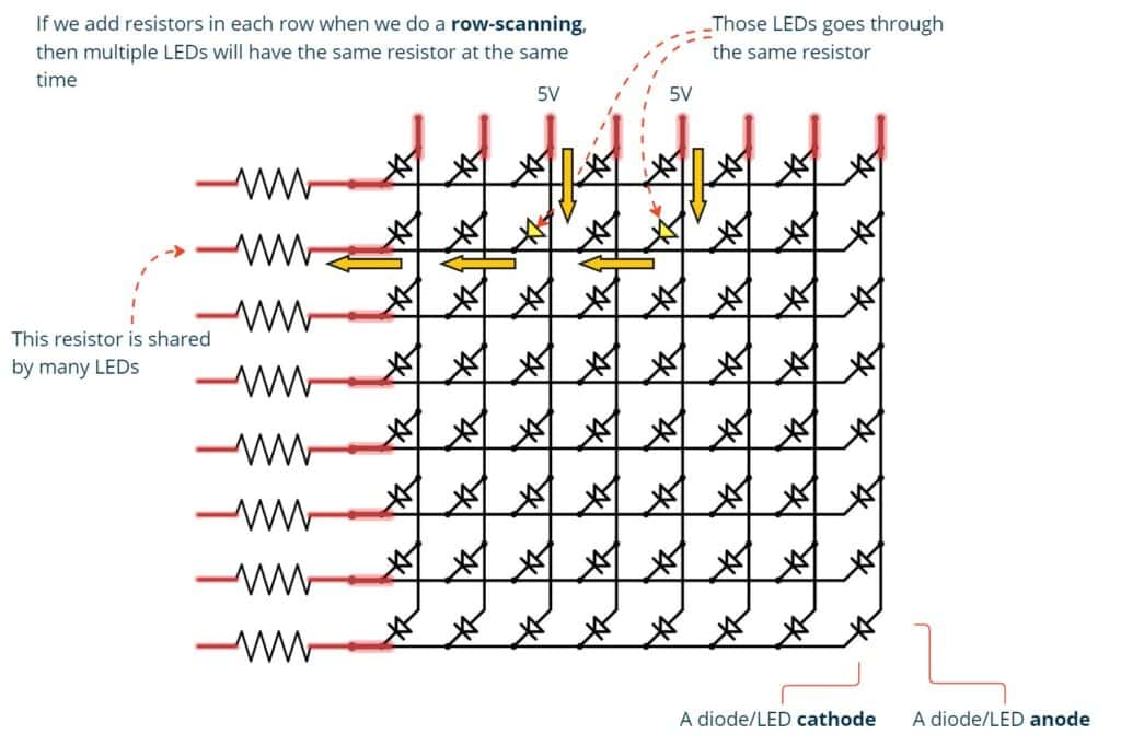
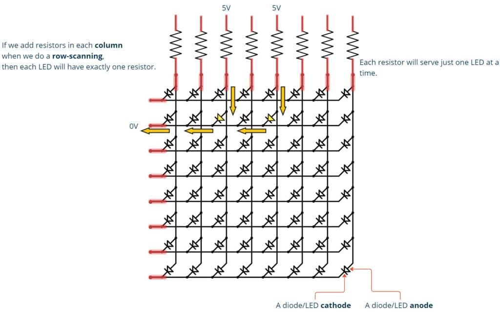
There is a correct way of putting resistors when controlling a display which requires scanning. The way of scanning determines where the resistors will be placed. If we scanning rows, the resistors have to be on the columns, and vice versa. Let’s see why this is the case.
Consider a row-scanning. If we place resistors in each row, then during the scanning of the first row, every illuminated LED will share the same resistor from that particular row:
The correct way when we perform a row-scanning is to position resistors in each column. This ensures that each LED is associated with only one resistor at any given time:
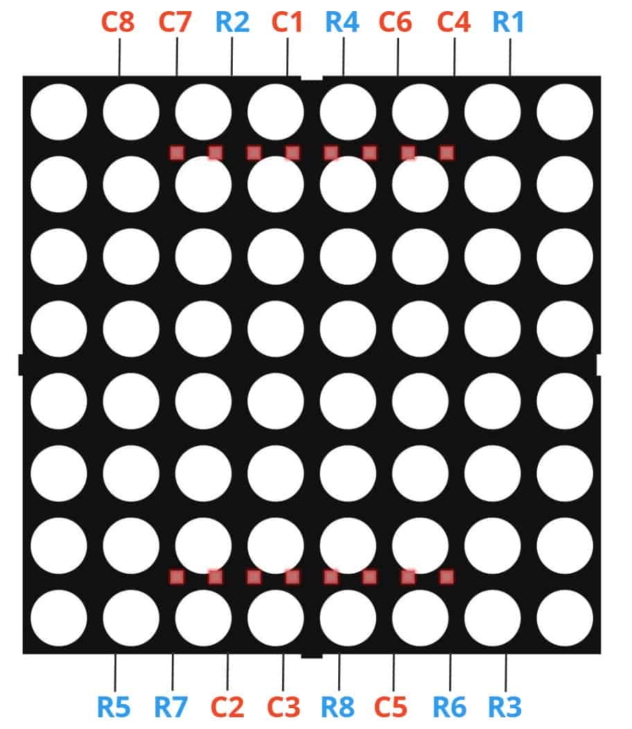
8×8 LED Display Pinout
In this section, we illustrate the pinout of various commonly used 8×8 LED Displays. The 8×8 LED Displays have 8 pins in one side and the other 8 pins on the other side. However, this does not mean that one side has the pins of rows and the other has pins for columns. The internal wiring makes the pinout a little bit more complicated.
1088AS
For the 1088AS Model, we have the following Pinout:
8×8 LED Display and Arduino
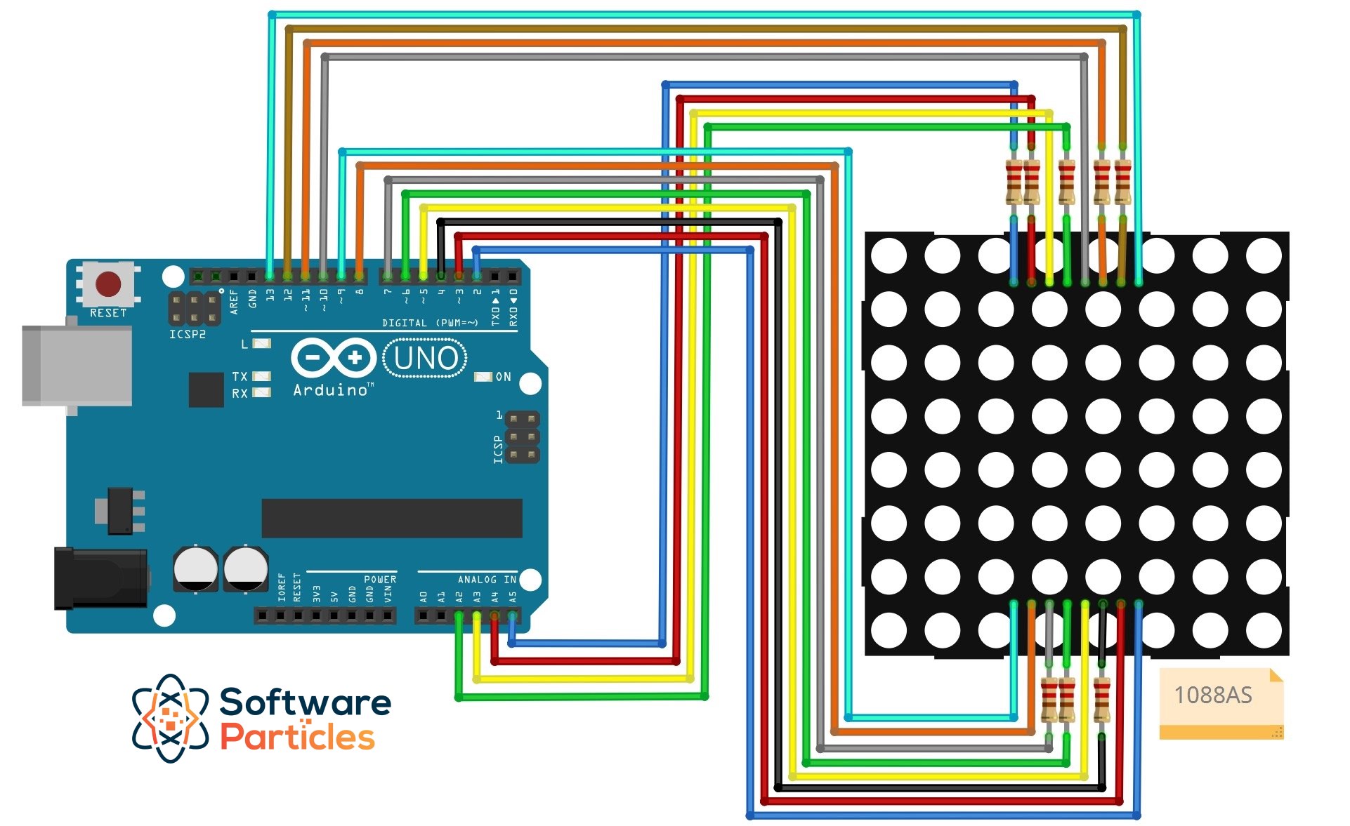
Schematic
The following schematic illustrates the wiring between the 1088AS LED Display using also resistors of 220 Ohms.
Code Implementation
To control an 8×8 LED Display using an Arduino, start by wiring the components as depicted in the previous schematic diagram.
Next, we configure two arrays that contain the rows and columns pin numbers.
// First configure the wiring between the pins
// of the LED Display with the Arduino.

// C for Column
int C1 = A2;
int C2 = 7;
int C3 = 6;
int C4 = 12;
int C5 = 4;
int C6 = 11;
int C7 = A4;
int C8 = A5;

// R for Rows
int R1 = 13;
int R2 = A3;
int R3 = 2;
int R4 = 10;
int R5 = 9;
int R6 = 3;
int R7 = 8;
int R8 = 5;
// ---

// Array of row pin numbers:
const int row[8] = { R1, R2, R3, R4, R5, R6, R7, R8 };

// Array of column pin numbers:
const int col[8] = { C1, C2, C3, C4, C5, C6, C7, C8 };
Within the setup function, we initialize a two-dimensional array that holds the state of the Display, set the state of the pins of the LED Display to LOW, so all LEDs will be turned off, and also initialize the values that indicate when a row/column is considered ON or OFF depending on whether the LED Display is row common cathode or not. For example, a row-common cathode LED Display will have the ROW_ON set to LOW and the COLUMN_ON set to HIGH.
// We define whether or not the LED Display is row common cathode.
#define ROW_CATHODE false

int pixels[8][8]; // We store the state of the LED Display.
// When a cell of the array is HIGH it means the LED will be turned ON and vise versa.

// We will set HIGH or LOW depending on whether the LED Display is common cathode or not.
int ROW_ON;
int ROW_OFF;
int COLUMN_ON;
int COLUMN_OFF;

void setup() {
  initializeCathodeAndAnodes();
  initializePins();
  initializePixelMatrix();
}
Below, the implementation of the initialization methods:
void initializeCathodeAndAnodes() {
  if (ROW_CATHODE) {
    ROW_ON = LOW;
    ROW_OFF = HIGH;

    COLUMN_ON = HIGH;
    COLUMN_OFF = LOW;
  } else {
    ROW_ON = HIGH;
    ROW_OFF = LOW;

    COLUMN_ON = LOW;
    COLUMN_OFF = HIGH;
  }
}

void initializePins() {
  for (int i = 0; i < 8; i++) {
    pinMode(col[i], OUTPUT);
    pinMode(row[i], OUTPUT);

    rowOFF(i);
  }
}

void initializePixelMatrix() {
  for (int x = 0; x < 8; x++) {
    for (int y = 0; y < 8; y++) {
      pixels[x][y] = LOW;
    }
  }
}
One last piece is the refreshing of the LED Display. In order to do that, we will do a row-scanning by reading the values of the pixels array and set the columns and rows appropriately:
void refreshScreen() {
  for (int r = 0; r < 8; r++) {
    allColumnsOFF();
    rowON(r);

    for (int c = 0; c < 8; c++) {
      int pixelState = pixels[r][c];

      if (pixelState == HIGH) columnON(c);
      else columnOFF(c);
    }

    // Let the LEDs of this row light up for a while.
    delayMicroseconds(50);
    rowOFF(r);
  }
}
The allColumnsOFF, rowON, rowOFF, columnON and columnOFF helper methods are defined below:
void allColumnsOFF() {
  digitalWrite(col[0], COLUMN_OFF);
  digitalWrite(col[1], COLUMN_OFF);
  digitalWrite(col[2], COLUMN_OFF);
  digitalWrite(col[3], COLUMN_OFF);
  digitalWrite(col[4], COLUMN_OFF);
  digitalWrite(col[5], COLUMN_OFF);
  digitalWrite(col[6], COLUMN_OFF);
  digitalWrite(col[7], COLUMN_OFF);
}

void rowON(int index) {
  digitalWrite(row[index], ROW_ON);
}

void rowOFF(int index) {
  digitalWrite(row[index], ROW_OFF);
}

void columnON(int index) {
  digitalWrite(col[index], COLUMN_ON);
}

void columnOFF(int index) {
  digitalWrite(col[index], COLUMN_OFF);
}
Now we are ready to control the 8×8 LED Display inside the loop function of the Arduino.
The code is available on GitHub
Examples
Below we use Arduino in order to demonstrate the capabilities of a 8×8 LED Matrix.
Turning ON a Specific LED
In this example, we control the rows and columns of the LED Matrix in order to illuminate the LED of the 4th row and 4th column. We will make use of the code we provided before, which controls the 8×8 LED Display and we will set the appropriate cell in the pixels array:
void loop(){
  pixels[3][3] = HIGH;
  refreshScreen();
}
This way, inside the refreshScreen function it will turn ON the appropriate row and column.
Alternatively, for a row common cathode 8×8 LED Display, without using the previous refreshScreen function, you can control the rows and columns using digitalWrite:
allColumnsOFF();
digitalWrite(row[3], LOW);
digitalWrite(col[3], HIGH);
Create a Moving Pixel
This example animates a pixel moving across the 8×8 LED Display. At any time, only one pixel is illuminated. For this to happen, we will hold two variables that store the coordinates of the current LED and we will increase or reset them accordingly as shown in the code below:
void loop() {
  if (count == 30) // This controls the 'speed' of the pixel.
  {
    pixels[x][y] = LOW; // We turn OFF the previous pixel.

    if (x == 7 && y == 7) // If we reached at the end of the display, reset.
    {
      x = 0;
      y = 0;
    } else if (y == 7) // If we reached at the end of the row, reset the column.
    {
      y = 0;
      x++; // Go to the next row.
    } else
    {
      y++; // Go to the next pixel.
    }

    pixels[x][y] = HIGH; // set the next pixel HIGH.
    count = 0;
  }

  refreshScreen();
  count++;
}
After uploading the previous code, the result is shown below:
Display 8×8 Icons
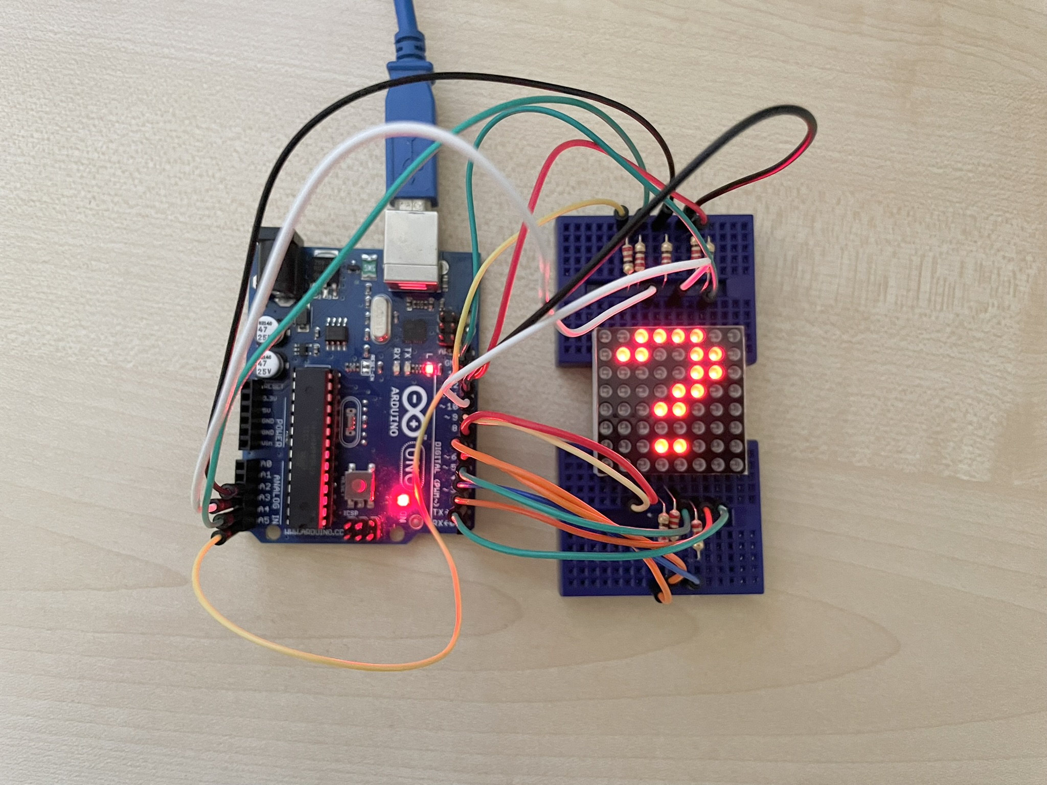
Although the 8×8 LED Matrix Display is very low resolution, we can display a large variety of icons for its size. You can find many 8×8 icons for an 8×8 LED Display at xantorohara.github.io/led-matrix-editor. In this example we will display a questionmark icon.
In order to display an icon, we set the appropriate cells of the pixels array to HIGH and then we call the refreshScreen to display the icon.
void loop()
{
  pixels[0][2] = HIGH;
  pixels[0][3] = HIGH;
  pixels[0][4] = HIGH;
  pixels[0][5] = HIGH;

  pixels[1][1] = HIGH;
  pixels[1][2] = HIGH;
  pixels[1][5] = HIGH;
  pixels[1][6] = HIGH;

  pixels[2][5] = HIGH;
  pixels[2][6] = HIGH;

  pixels[3][4] = HIGH;
  pixels[3][5] = HIGH;

  pixels[4][3] = HIGH;
  pixels[4][4] = HIGH;

  pixels[6][3] = HIGH;
  pixels[6][4] = HIGH;

  pixels[1][1] = HIGH;
  pixels[2][2] = HIGH;
  pixels[3][3] = HIGH;
  pixels[4][4] = HIGH;
  pixels[5][5] = HIGH;
  pixels[6][6] = HIGH;
  pixels[7][7] = HIGH;

  refreshScreen();
}
The result is shown below:
Display Icons using the EightByEightDisplay Library
We can use the EightByEightDisplay library that makes displaying icons on the 8×8 LED Display a lot easier. The library can be found on GitHub. In this example, two icons, a questionmark and a smile, are displayed alternately:
#include "EightByEightDisplay.h"

EightByEightDisplay display;

int C1 = A2;
int C2 = 7;
int C3 = 6;
int C4 = 12;
int C5 = 4;
int C6 = 11;
int C7 = A4;
int C8 = A5;

// R for Rows
int R1 = 13;
int R2 = A3;
int R3 = 2;
int R4 = 10;
int R5 = 9;
int R6 = 3;
int R7 = 8;
int R8 = 5;

uint8_t questionmark[8][8] = {
  { LOW, LOW, HIGH, HIGH, HIGH, HIGH, LOW, LOW },
  { LOW, HIGH, HIGH, LOW, LOW, HIGH, HIGH, LOW },
  { LOW, LOW, LOW, LOW, LOW, HIGH, HIGH, LOW },
  { LOW, LOW, LOW, LOW, HIGH, HIGH, LOW, LOW },
  { LOW, LOW, LOW, HIGH, HIGH, LOW, LOW, LOW },
  { LOW, LOW, LOW, LOW, LOW, LOW, LOW, LOW },
  { LOW, LOW, LOW, HIGH, HIGH, LOW, LOW, LOW },
  { LOW, LOW, LOW, LOW, LOW, LOW, LOW, LOW },
};

uint8_t smile[8][8] = {
  { LOW, LOW, HIGH, HIGH, HIGH, HIGH, LOW, LOW },
  { LOW, HIGH, LOW, LOW, LOW, LOW, HIGH, LOW },
  { HIGH, LOW, HIGH, LOW, LOW, HIGH, LOW, HIGH },
  { HIGH, LOW, LOW, LOW, LOW, LOW, LOW, HIGH },
  { HIGH, LOW, HIGH, LOW, LOW, HIGH, LOW, HIGH },
  { HIGH, LOW, LOW, HIGH, HIGH, LOW, LOW, HIGH },
  { LOW, HIGH, LOW, LOW, LOW, LOW, HIGH, LOW },
  { LOW, LOW, HIGH, HIGH, HIGH, HIGH, LOW, LOW },
};

void setup() {
  uint8_t row[8] = { R1, R2, R3, R4, R5, R6, R7, R8 };
  uint8_t col[8] = { C1, C2, C3, C4, C5, C6, C7, C8 };
  display.init(1, row, col);
}

int count = 0;
void loop() {

  if (count == 1000) {
    display.update(smile);
  } else if (count == 2000) {
    display.update(questionmark);
    count = 0;
  }

  display.refresh();
  count++;
}
The result is shown below: