 and LSBFIRST (Least Significant Bit)")
In this article, we explain the concepts of MSB (Most Significant Bit) and LSB (Least Significant Bit), along with MSBFIRST and LSBFIRST. Finally, we provide a demonstration of how the use of MSBFIRST and LSBFIRST affects the outputs of shift registers.
If you want to learn the basics of how shift registers work, check the Learn How Shift Registers work and how to use them using Arduino
If you want to learn how the 74HC595 works and how to control it using an Arduino check the article Use 74HC595 Shift Register With Arduino
MSB and LSB
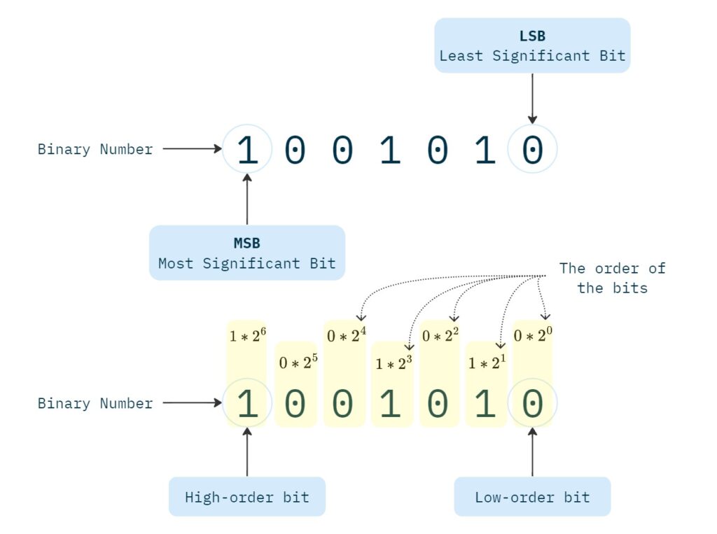
The MSB, or Most Significant Bit, refers to a specific bit in a binary number. The Most Significant Bit, holds the higher weight or value in the binary representation. It is also known as the left-most bit or higher-order bit. In contrast, the LSB, or Least Significant Bit, refers to the lowest value bit in a number, making it the right-most bit or the low-order bit.
MSBFIRST and LSBFIRST
In the serial transfer of data in electronics, when transmitting a binary number, we usually have to decide about whether to start the transfer from the leftmost or rightmost bit. This is referred to MSBFIRST and LSBFIRST.
For example, consider the shiftOut function in Arduino, which transfers a byte of data one bit at a time. The function includes a parameter (bitOrder) that allows us to specify whether the byte should be sent starting from its MSB or LSB.
shiftOut(dataPin, clockPin, bitOrder, value)Configuring this parameter becomes more important when working with various digital components, such as shift registers. For instance, transferring a byte to a shift register starting from its Most Significant Bit will yield a different result compared to starting from its Least Significant Bit.
74HC595 Shift Register with MSBFIRST and LSBFIRST
In this section, we explore two distinct examples of utilizing the shiftOut function with MSBFIRST and LSBFIRST parameters to write a binary number to the 74HC595 shift register. The same principles apply across all other shift register models.
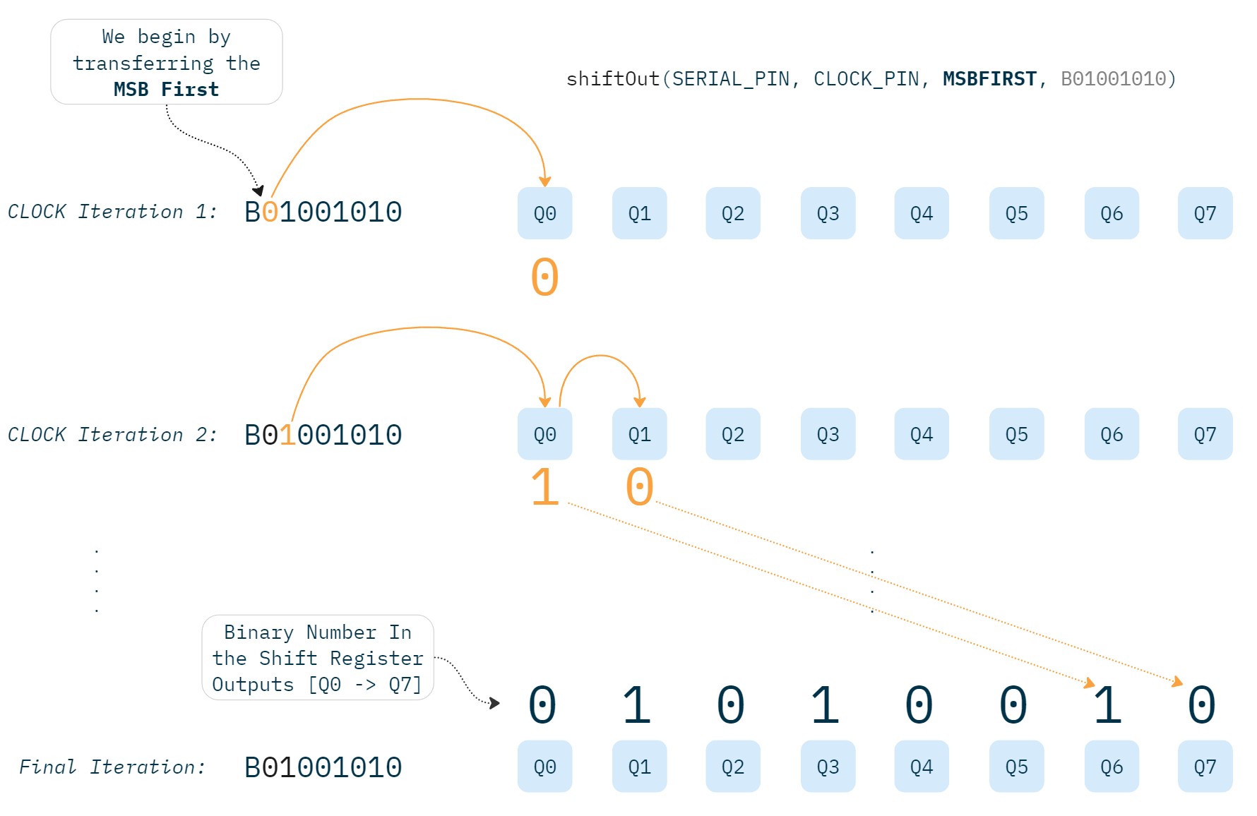
In the code below, we write the 8-bit binary number ‘01001010’ to the shift register with MSBFIRST configuration:
#define SERIAL_PIN 4
#define LATCH 3
#define CLOCK_PIN 2

void setup() {
  pinMode(SERIAL_PIN, OUTPUT);
  pinMode(LATCH, OUTPUT);
  pinMode(CLOCK_PIN, OUTPUT);

  digitalWrite(LATCH, LOW);
  shiftOut(SERIAL_PIN, CLOCK_PIN, MSBFIRST, B01001010);
  digitalWrite(LATCH, HIGH);
}

void loop() { }
In this configuration, the shift register’s outputs will have the leftmost digit of the binary number ‘01001010’ in the Q7 output, with its rightmost digit at the Q0 output after the transfer.
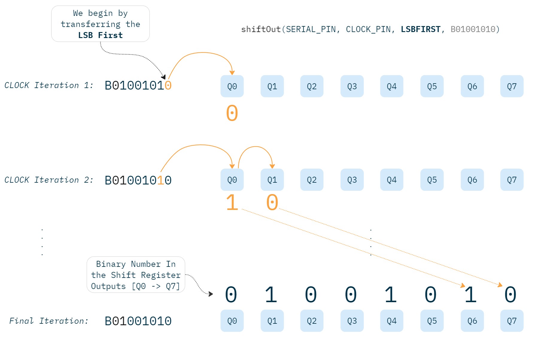
Similarly, the code snippet below, illustrates writing the binary number ‘01001010’ to the shift register, but this time with LSBFIRST configuration:
#define SERIAL_PIN 4
#define LATCH 3
#define CLOCK_PIN 2

void setup() {
  pinMode(SERIAL_PIN, OUTPUT);
  pinMode(LATCH, OUTPUT);
  pinMode(CLOCK_PIN, OUTPUT);

  digitalWrite(LATCH, LOW);
  shiftOut(SERIAL_PIN, CLOCK_PIN, LSBFIRST, B01001010);
  digitalWrite(LATCH, HIGH);
}

void loop() { }
With LSBFIRST, we will have a different outcome, the shiftOut function will begin to transfer the number to the shift register by beginning from its rightmost digit. This way, the rightmost digit of the number ‘01001010’ will be located in the Q7 output, while its leftmost digit will appear at the Q0 output after the transfer.
If you want to learn how the 74HC595 works and how to control it using an Arduino check the article Use 74HC595 Shift Register With Arduino