

A shift register is a digital component, which consists of digital gates and flip flops, capable of retaining memory and shift the output one bit at a time. In this article we will learn how shift registers work, how to use them, and how to increase the outputs of a microcontroller like Arduino.
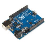
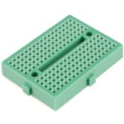
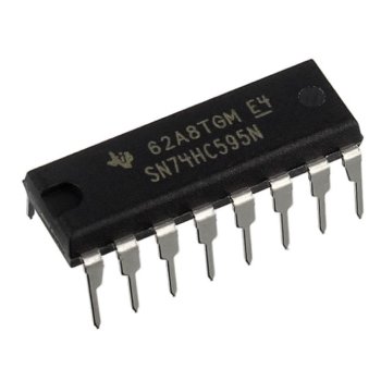
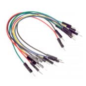
Parts Used
* This website includes affiliate product links. We may earn a commission if you make a purchase after clicking on one of these links. Your support is greatly appreciated!
How Shift Register Works
A shift register consists of digital gates and multiple flip-flop components. Flip-flops have the ability to store one bit of memory. By connecting several flip-flops in series, shift registers can store multiple bits of memory, typically controlled by only two or three inputs.
Flip Flops
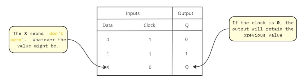
First, we have to gain some basic knowledge of what a flip-flop does. A flip-flop has two inputs, one for clock (CLK or S) and one for serial input/data (R). Additionally, it has two outputs. One is the currently stored bit (Q), and the other is the output inverted (Q’). Below is a representation of a flip-flop component and its truth table:
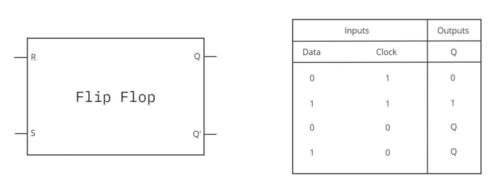
When the clock signal is set to 1, whatever value is in the Data, it is transferred to the output Q. After that, when the Clock signal returns to 0, the component will remember the last value of the Data. While the clock signal remains 0, the Data input has no effect. Only when the clock signal is set to 1 (edge triggered), the component gets the Data value and transfer it to the output Q. In other words, the component stores the value in the Data input when the clock is set to 1, otherwise the Data input has no effect.
Connecting multiple Flip-Flops
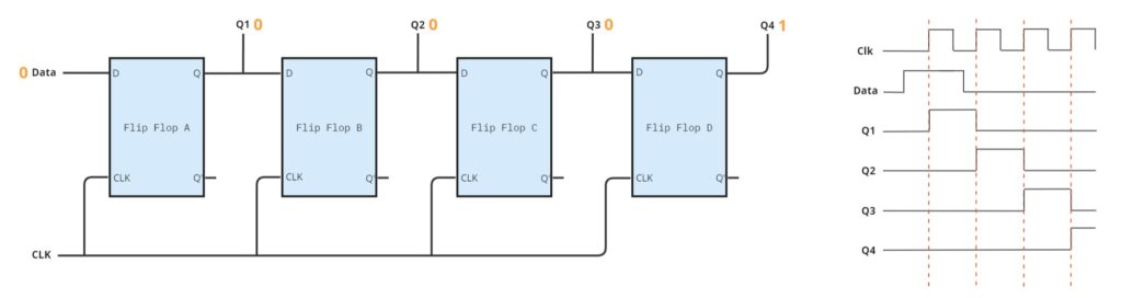
We can connect multiple flip-flops together by wiring their CLK inputs. Additionally, we connect the output of each flip-flop to the Data input of the next one. This way, we can transfer bits from one flip-flop to another. The rate at which bits move from the one flip-flop to the next is controlled by the CLK speed. This creates a shifting effect where the leftmost flip-flop’s first bit is moved into the next one every time the CLK is set to 1.
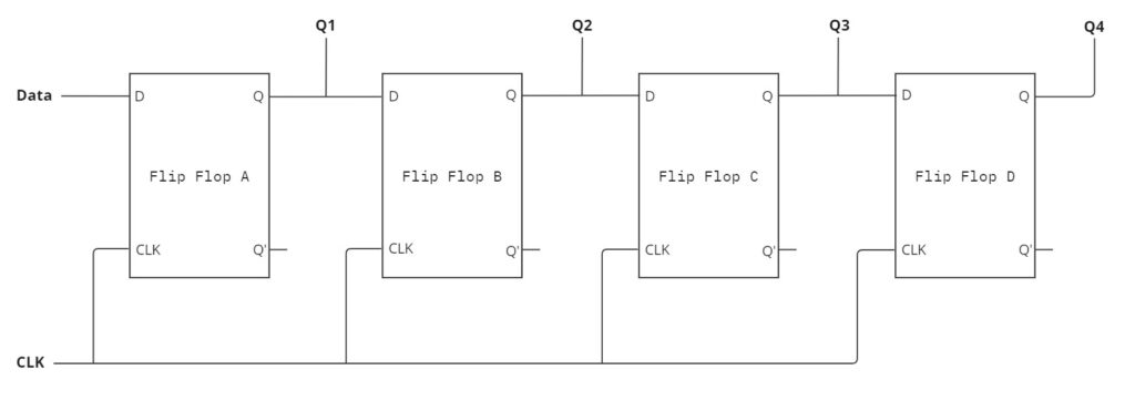
Usually, the Q’ inverted outputs are not utilized in a shift register.
Next, we examine how a signal progresses from one flip-flop to the next over time.
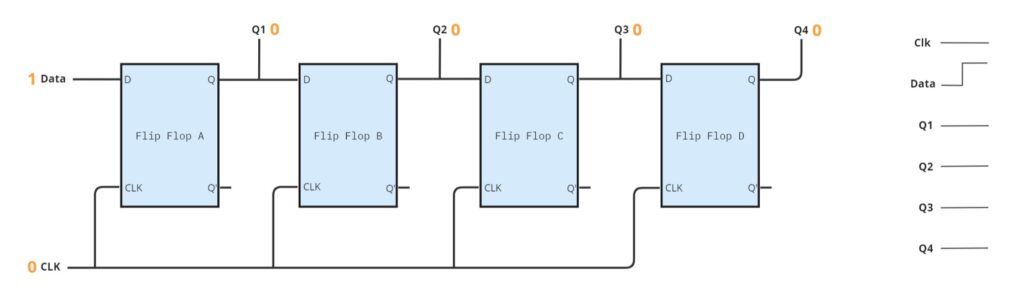
First, the shift register has no inputs set.
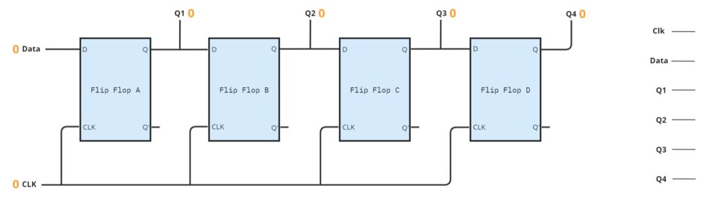
Then, we set the Data to 1. However, since the clock is still at 0, no data will be transferred into the shift register.
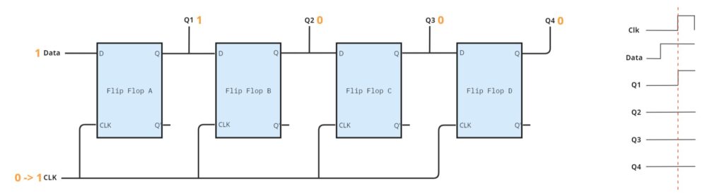
When the Clock is set to 1, each flip flop stores the data signal and outputs it to the Q output. Flip-flops are edge triggered, meaning they transfer data to the output Q only when the clock changes from 0 to 1.
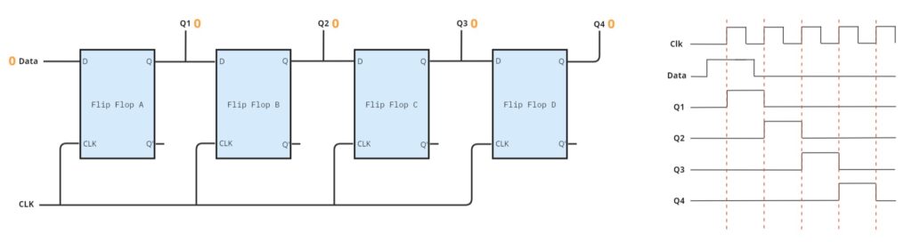
Next, we set the data to 0, and then trigger the clock again. The Q1 Output will receive the new value of the Data, which is 0, but the Flip Flop B will transfer the 1 from the output of the first Flip Flop to its output.
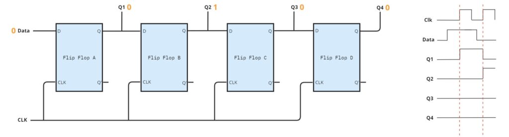
In the next clock trigger, the Flip Flop B will transfer the 0 from its input to the Q2 output, while the Flip Flop C will get the 1 from its input and will transfer to its output Q3. The shifting pattern begins to emerge.
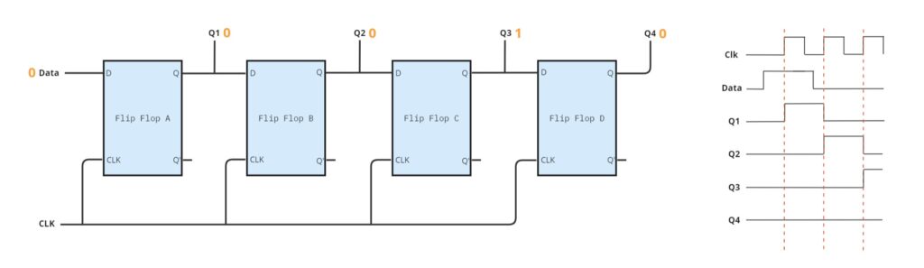
Similarly, in the next clock change, the Q3 will be set to 0 and the Q4 to 1.
Finally, in the next clock edge, the Q4 will be set to 0, completing the shifting of the one bit that initially started as input.
Latch
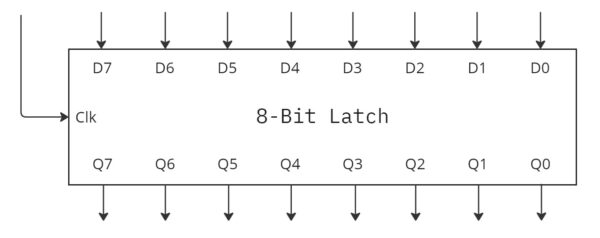
A latch is a digital component that stores a bit for future use. When the clock is set to 1, the previously set input value is transferred to the output.
To create N-bit latches, we can connect multiple 1-bit latches by linking their clock inputs. We can use those type of components when we need to collect output from other digital components and provide them all at the same time.
Latches and shift registers are often used together. A shift register with a latch has an extra set of memory. After the shift register finishes shifting the bits, we set the latch’s clock to get the resulting value. This is important because, in many cases, we want a specific output from the shift register, however, to reach that output, the shift register may take several cycles, and during this time, it might change its outputs multiple times. This could cause issues for the components directly connected to the output of the shift register. Having an intermediary storage unit that can collect and provide us only the final state may be necessary.
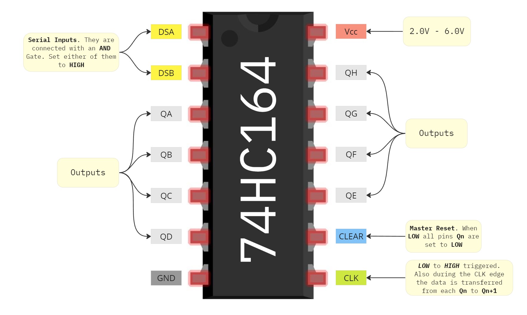
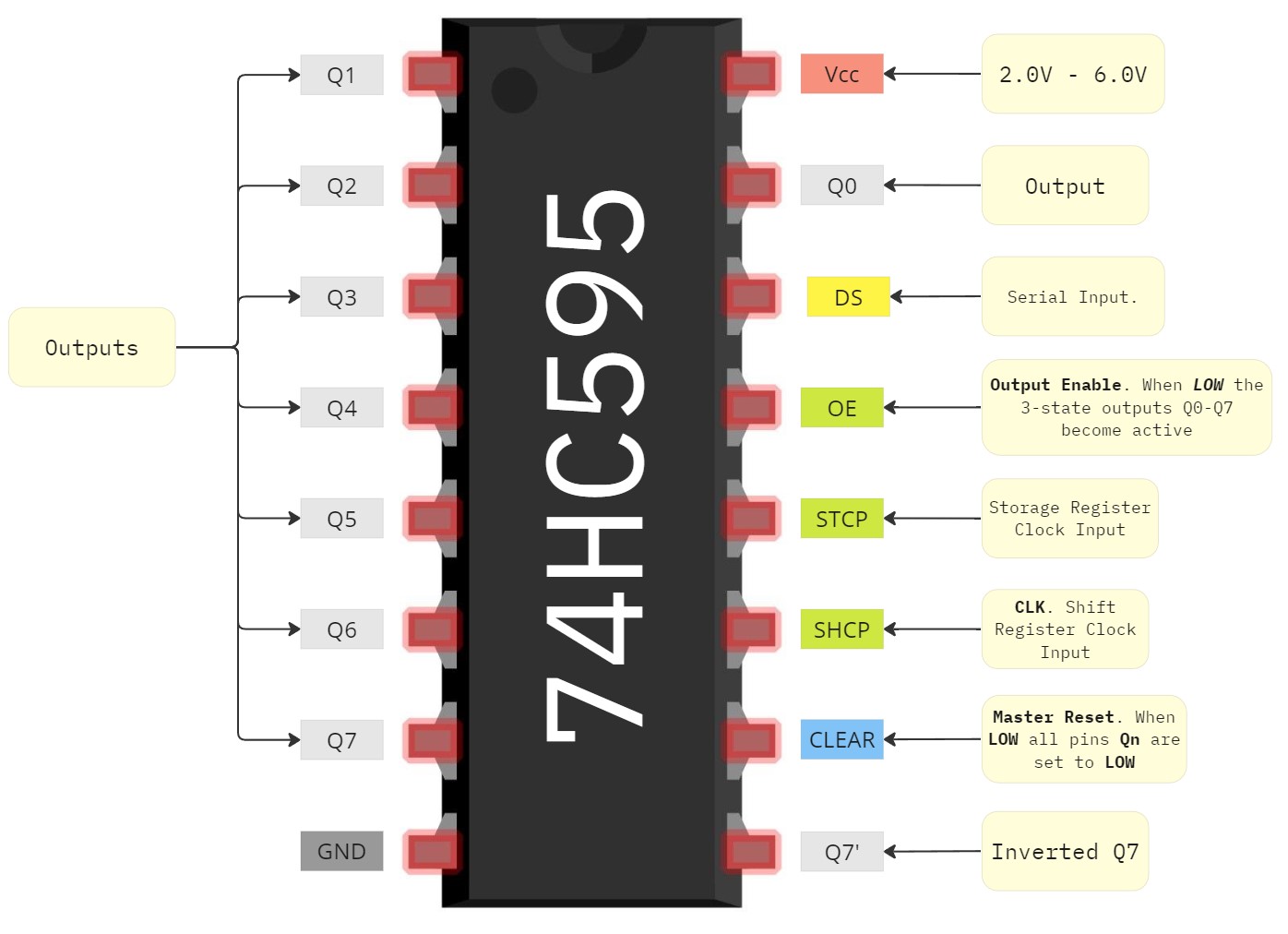
74HC164 and 74HC595 Shift Registers PINOUT
There are many types of shift registers with slightly different inputs and outputs, yet they all share common characteristics. Below, we explore the pinout of the 74HC164 and 74HC595 families of shift registers.
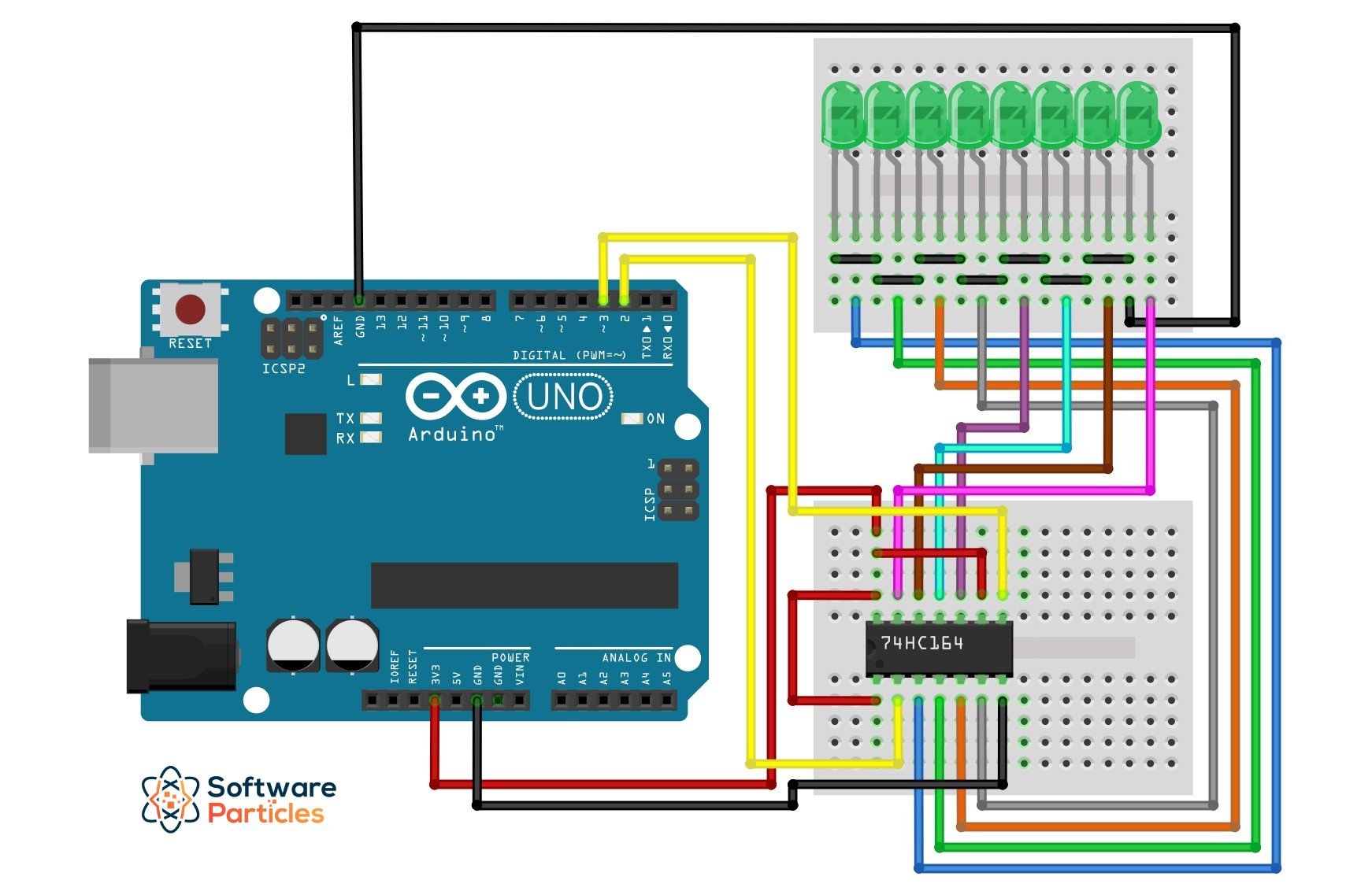
Arduino and 74HC164 Connectivity
Below, we display how to connect the 74HC164 shift register with an Arduino. We’ve also directly connected LEDs to the shift register’s outputs, allowing us to visually inspect the outputs later.
Shifting a Bit from the Leftmost Output to the Rightmost Output
In this example, we demonstrate how to use the 74HC164 shift register to shift a bit from the first output to the last and then repeat the process. The circuit is displayed in the previous image. First, we initialize two Arduino pins as OUTPUT, one for the Serial Input (Data) and the other for the Clock. Then, inside the loop function, the first action is to set Data to HIGH and transfer it to the shift register. Later, in a for loop we set the Clock from LOW to HIGH in order to shift the bit to the next output.
#define data 2
#define clock 3
void setup() {
pinMode(clock, OUTPUT); // Set the Clock pin as output.
pinMode(data , OUTPUT); // Set the Data pin as output.
}
void loop() {
InsertFirstBit();
// Trigger the clock 7 more times to fully shift the bit to the end.
for(int i = 0; i < 7; i++)
{
Clock();
delay(100);
}
}
void InsertFirstBit(){
digitalWrite(data, HIGH);
Clock(); // Transfer the bit from Data to the first output.
digitalWrite(data, LOW);
}
void Clock(){
// When we set the clock HIGH, the shift register shifts the output by one bit.
digitalWrite(clock, HIGH);
delay(1);
digitalWrite(clock, LOW);
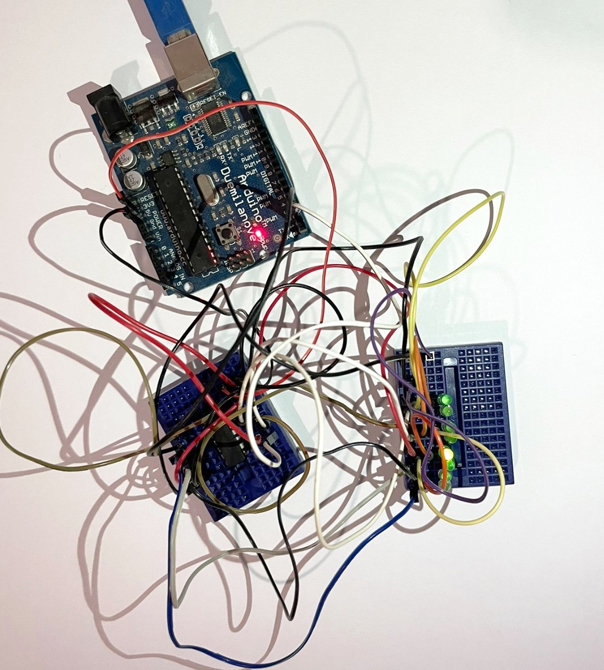
}The resulting effect is shown below:
ShiftOut Function
Another way to achieve a similar effect is by utilizing the shiftOut function provided by Arduino. By using this function we can shift out a byte of data one bit at a time. Each bit of the byte we want to write to the shift register is set to the dataPin , which is configured in the shiftOut function. Also, we set a pin (clockPin) to be used as clock. Finally, we can control the direction in which the byte will be written by configuring either LSBFIRST or MSBFIRST in the bitOrder parameter.
The syntax for the shiftOut function is as follows:
shiftOut(dataPin, clockPin, bitOrder, value)The value is a binary number. Below, we demonstrate the same effect as in the previous example, but we make use of the shiftOut function instead of manually triggering the clock and setting the data input.
#define data 2
#define clock 3

void setup() {
  pinMode(clock, OUTPUT); // Set the Clock pin as output.
  pinMode(data , OUTPUT); // Set the Data pin as output.
}

int snapshots[8] = {
  B00000001,
  B00000010,
  B00000100,
  B00001000,
  B00010000,
  B00100000,
  B01000000,
  B10000000
};

void loop() {
  for (int count = 0; count < 8; count++) {
    delay(100);
    shiftOut(data, clock, MSBFIRST, snapshots[count]);
  }
}
Please note that using the shiftOut function with a shift register without a latch, will cause the outputs to flicker.
How to Increase the Number of Arduino Pins
By using a shift register, we can increase the number of outputs of a microcontroller like Arduino. With just two inputs from Arduino, for Data and Clock, we can manipulate the eight outputs of the shift register. These outputs can be treated as separate outputs to control other devices.
It’s important to note that you should not use the outputs of a shift register to power high-current devices like motors. Make sure to use an external power source and amplify the signal independently before reaching the final device.
Preferably, we can use a shift register like the 74HC595, which includes an internal latch component. When we shift bits in the shift register to reach the desired output, the final outputs of the shift register won’t change until we set the latch. This prevents any unintended side effects on components connected to the outputs of the shift register.
In this example, we will show how we can control a 1-Digit 7-Segment LED Display by using only two Arduino outputs. Such a display component typically has 8 inputs, and we will use the outputs of the 74HC164 shift register to control it.
Learn How a 4-Digit 7-Segment LED Display Works and how to control it using an Arduino
First, let’s take a look at the Pinout of a 1-Digit 7-Segment Display:
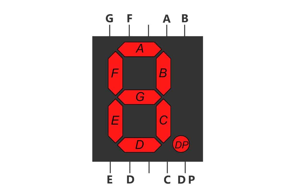
Next, we make the following wiring between Arduino, the 74HC164 shift register, and the 7-Segment LED Display:
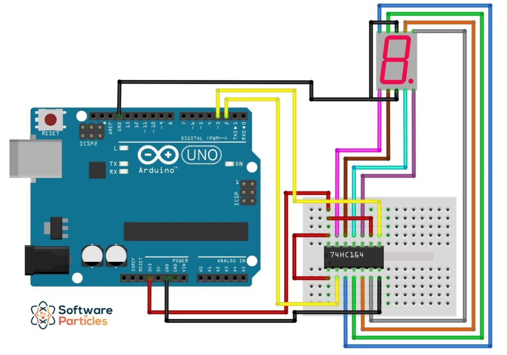
As shown in the previous image, we utilize only two Arduino outputs to control an 8-input component.
Finally, we can use the shiftOut Arduino function to control the LED Display, as shown in the code below:
#define data 2
#define clock 3

void setup() {
  pinMode(clock, OUTPUT); // Set the Clock pin as output.
  pinMode(data , OUTPUT); // Set the Data pin as output.
}

// Configuration/Wiring between shift register and LED Display:
// Shift Register Output - LED Display Input
// QA -------------------> G
// QB -------------------> F
// QC -------------------> A
// QD -------------------> B
// QE -------------------> DP // Decimal Point
// QF -------------------> C
// QG -------------------> D
// QH -------------------> E

// This array stores the bit configuration (HIGH, LOW) for each of the
// display's numbers.
int numbers[10] = {
  B01110111, // 0
  B00010100, // 1
  B10110010, // 2
  B10110110, // 3
  B11010100, // 4
  B11100110, // 5
  B11000111, // 6
  B00110100, // 7
  B11110111, // 8
  B11110100, // 9
};

void loop() {
  // Display every number in the LED Display.
  for (int count = 0; count < 10; count++) {
      delay(500);
      // Set the output that corresponds to the current digit.
      shiftOut(data, clock, MSBFIRST, numbers[count]);
    }
}
This way, we can have as many outputs as we need from a microcontroller by using shift registers.


1 Comment
excellent presentation