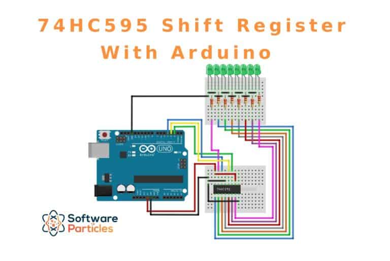
In this article, we will explore the use of the 74HC595 Shift Register with an Arduino to control 8 LEDs. This demonstration illustrates how we can expand the number of available Arduino pins, allowing us to manage components that require multiple inputs.
The 74HC595 Shift Register serves as a valuable component when you need to control several outputs using only a limited number of Arduino pins.
If you want to learn the basics of how shift registers work, check the Learn How Shift Registers work and how to use them using Arduino
The code is available on GitHub
74HC595 Architecture
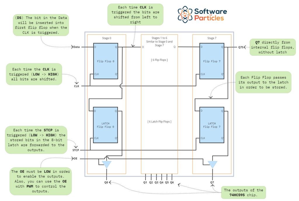
The internal architecture of the 74HC595 consist of 8 flip-flops for shifting the bits, 8 flip-flops for the storage register (latch), and various logic gates. The storage register acts as a latch, retaining the final value and transmitting it to the component’s outputs. This is controlled by the STCP (Storage Register Clock Input). With the 74HC595, you can shift bits without affecting the output, thanks to the embedded 8-bit latch.
The SHCP (Shift Register Clock Input) shifts one bit within the component with every change in its signal (from LOW to HIGH). This allows us to shift bits and then transmit the final result to the device’s outputs.
The internal logic of the component is shown below:
74HC595 Pinout
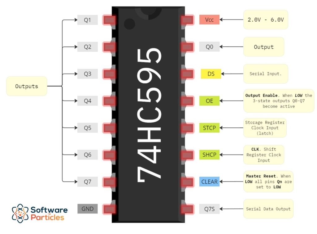
Below we illustrate the Pinout of the 74HC595 chip.
Arduino and 74HC595 Wiring
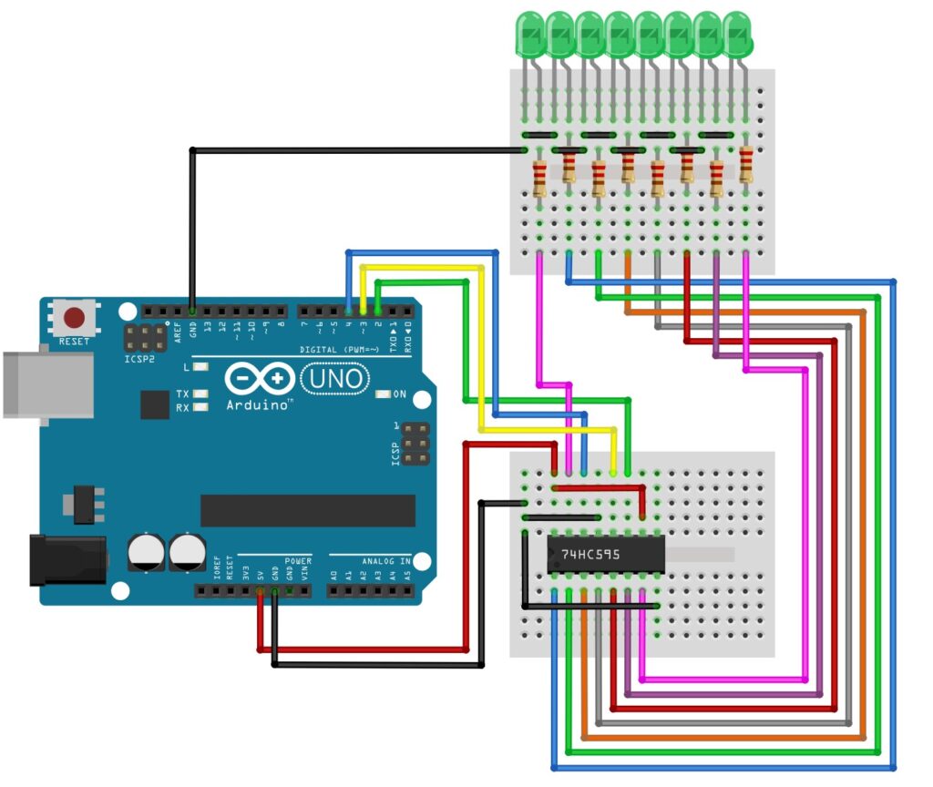
The wiring below illustrate a use case for controlling 8 LEDs by using only 3 outputs of the Arduino as inputs to the 74HC595 shift register. Also, we use 8 x 220Ohm resistors in order to protect the LEDs.
74HC595 Usage Example
To use the 74HC595 with Arduino, we start by declaring the pins we’ll use (in this example, pins 2, 3, and 4) as OUTPUT. Then, by using the shiftOut function, we simply provide the pin numbers as parameters along with the number we want to write (to transfer to the shift register).
Before calling the shiftOut function, we have to set the STCP (Storage Register Clock Input) to LOW. This action retains the state of the shift register’s output. After calling shiftOut, we set the STCP to HIGH to forward the bits from the internal latch to the final outputs. While the shiftOut changes the internal state of the shift register, the output will not be affected, until we set the STCP to HIGH.
The following code demonstrates a simple loop that iterates through numbers from 0 to 255, transfering them to the 74HC595 and displaying the binary result by using the LEDs.
#define SHCP 2 // Clock
#define STCP 3 // Storage Register Clock Input (latch)
#define DS 4 // Serial Input (Data)

void setup() {
  pinMode(SHCP, OUTPUT);
  pinMode(STCP, OUTPUT);
  pinMode(DS, OUTPUT);
}

void loop() {
  for (int n = 0; n < 256; n++) {
    digitalWrite(STCP, LOW); // hold the value.
    shiftOut(DS, SHCP, MSBFIRST, n);
    digitalWrite(STCP, HIGH); // flush the value to the outputs.
    delay(50);
  }
}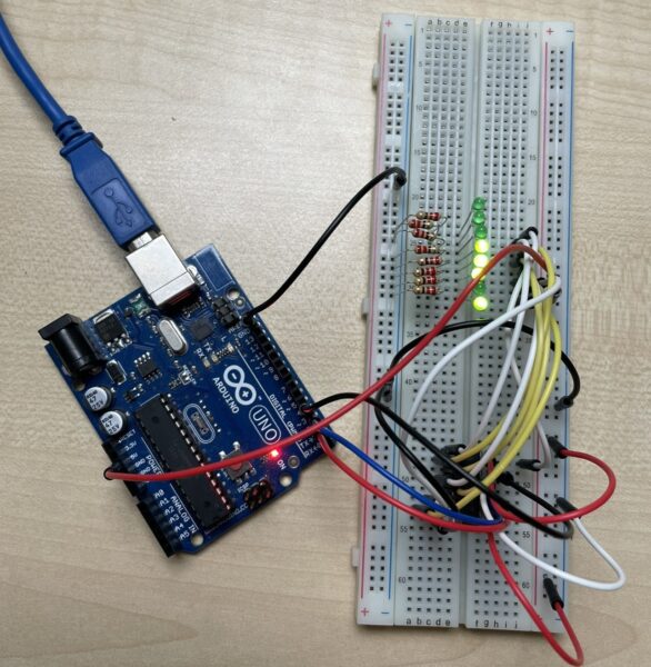
The final effect of uploading the code to Arduino is shown below:
74HC595 C++ Library
To simplify the usage of the 74HC595 Shift Register, we can create a C++ library, named SR_74HC595, which encapsulates the complexity of the chip.
The SR_74HC595 library is available on GitHub
First, we create a header file that defines the functions and the properties the library will have. Among them, the most important ones is the write function, where we set the number to be written to the shift register and the enableAutoFlush, disableAutoFlush where we set whether or not to trigger the clock of the internal latch (after we write a number) in order to forward the value of the shift register to its outputs automatically. We can also manually hold and flush the value to the outputs by using the respective functions. Lastly, the configure function configures the module, by setting the pins that will be used.
#ifndef SR_74HC595_H
#define SR_74HC595_H

#if defined(ARDUINO) && ARDUINO >= 100
#include "Arduino.h"
#else
#include "WProgram.h"
#endif

class SR_74HC595Module {
public:

  SR_74HC595Module();

  /*
    DS = serialPin
    OE = outputEnablePin
    STCP = storageRegisterClockPin = latch
    SHCP = clockPin = CLK
  */
  void configure(uint8_t serialPin, uint8_t outputEnablePin, uint8_t storageRegisterClockPin, uint8_t clockPin);

  void write(int value);
  void flush();
  void hold();
  void enableAutoFlush();
  void disableAutoFlush();

private:
  uint8_t _serialPin;
  uint8_t _outputEnablePin;
  uint8_t _storageRegisterClockPin;
  uint8_t _clockPin;

  bool _autoFlush;
};

#endif
Below, we present the implementation of the SR_74HC595.h header file.
#include "SR_74HC595.h"

SR_74HC595Module::SR_74HC595Module() {
}

void SR_74HC595Module::configure(uint8_t serialPin, uint8_t outputEnablePin, uint8_t storageRegisterClockPin, uint8_t clockPin) {
  _serialPin = serialPin;
  _outputEnablePin = outputEnablePin;
  _storageRegisterClockPin = storageRegisterClockPin;
  _clockPin = clockPin;

  pinMode(_storageRegisterClockPin, OUTPUT);
  if (_outputEnablePin != 0)
    pinMode(_outputEnablePin, OUTPUT);
  pinMode(_clockPin, OUTPUT);
  pinMode(_serialPin, OUTPUT);

  _autoFlush = false;
}

void SR_74HC595Module::write(int value) {
  hold();

  shiftOut(_serialPin, _clockPin, MSBFIRST, value);

  if (_autoFlush == true)
    flush();
}

void SR_74HC595Module::hold() {
  digitalWrite(_storageRegisterClockPin, LOW);
}

void SR_74HC595Module::flush() {
  digitalWrite(_storageRegisterClockPin, HIGH);
}

void SR_74HC595Module::enableAutoFlush() {
  _autoFlush = true;
}

void SR_74HC595Module::disableAutoFlush() {
  _autoFlush = false;
}
We can use the library above (ignoring the OE input in this case), in an Arduino project by importing the library and using a SR_74HC595Module object in order to control the 74HC595 chip. A simple example that shows the binary representations of numbers from 0 to 255 is shown below:
#include "SR_74HC595.h"

SR_74HC595Module shiftRegisterModule;

void setup() {
  shiftRegisterModule.configure(4, 0, 3, 2);
  shiftRegisterModule.enableAutoFlush();
}

void loop() {
  for (int n = 0; n < 256; n++) {
    shiftRegisterModule.write(n);
    delay(50);
  }
}
This way, we can encapsulate the module into a library making it easier and more reusable.

