

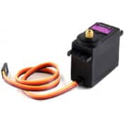
A Servo Motor is a rotary ( or linear ) actuator, typically with high torque and low angular velocity. Its main advantage lies in its internal controller that enables us to control its angular position or velocity easily, making it suitable for applications that demand precise control over angular or linear position, velocity, and acceleration. Servo motors are used in various applications, ranging from robotics and industrial automation to camera stabilizers. In this article we explore the inner mechanics of servo motors, providing insights into how they function. Additionally, we will showcase examples of how these motors can be controlled using an Arduino Board.
Parts Used
* This website includes affiliate product links. We may earn a commission if you make a purchase after clicking on one of these links. Your support is greatly appreciated!
Introduction
Servo motors are the most popular choice when it comes to adding precise motion to our projects. One of their advantages is that they come with an internal controller/driver, making them easy to control directly from an Arduino without needing any external modules or messy wiring. They can be used to control wing flaps, legs in a hexapod robot, the steering of an RC Car, the movement of a wheeled robot and many more.
Moreover, servo motors are available in various shapes and types. In this article, we will explore two popular types: the Continuous Rotation and Angular Servo motors.
Continuous Rotation Servo
The Continuous Rotation servo allows us to control their rotational speed. By adjusting the input signal to the servo, we can change its rotational speed. These servos are suitable for applications where a constant speed is required, such as in the movement of wheeled robots.
Angular Position Servo
On the other hand, there are servos that provide precise control over the position of their shaft. The frequency of the input signal instructs the motor to turn to a specific position. Typically, their range covers up to 180 degrees, but other servos can reach up to 360 degrees. These servos are suitable for applications where we need to rotate something to specific angle such as in robot arms where each joint can be controlled by this kind of servo.
How a Servo Motor Works
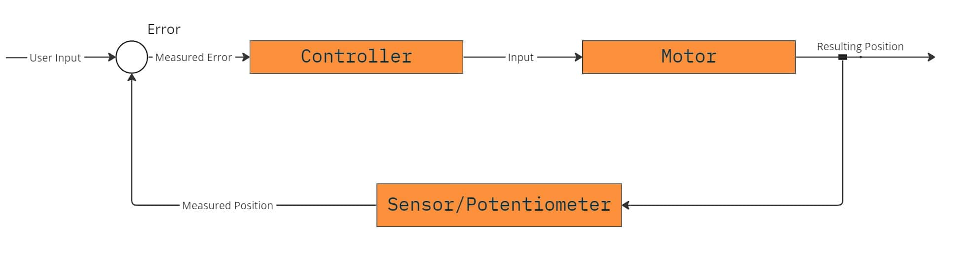
Servo motors are Closed Loop Control systems. This means they have a sensor, such as a potentiometer or an encoder, that tracks the position of the shaft. The sensor sends this information, which then adjusts the motor’s speed accordingly. This closed-loop system ensures that the motor reaches the desired position accurately.
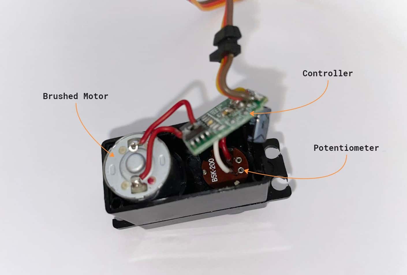
Below, we can see the internal components of the MG996R servo motor.
How a servo motor achieve its high torque
Servo motors are known for their high torque output in the shaft. This is achieved using different gears that reduce the rotational speed of the motor while increasing the final torque. In the video below we can observe the movement of the starting high speed gear (on the right) that is transferred through intermediate gears to the final gear that contains the servo motor shaft (on the left).
How to Control a Servo Motor using Arduino
Servo motors are controlled using Pulse Width Modulated (PWM) signals as inputs. The duration of the pulse directly determines the rotation of the servos. A short pulse of 1 ms or less makes the servo rotate to one end, while a slightly longer pulse of around 2 ms rotates it to the opposite end. These extreme positions represent the limits of the servo’s movement range. Within this range, servos interpret the pulse width and rotate to a position proportional to it. For example, a 1.5 ms pulse positions the servo halfway between its extreme positions.
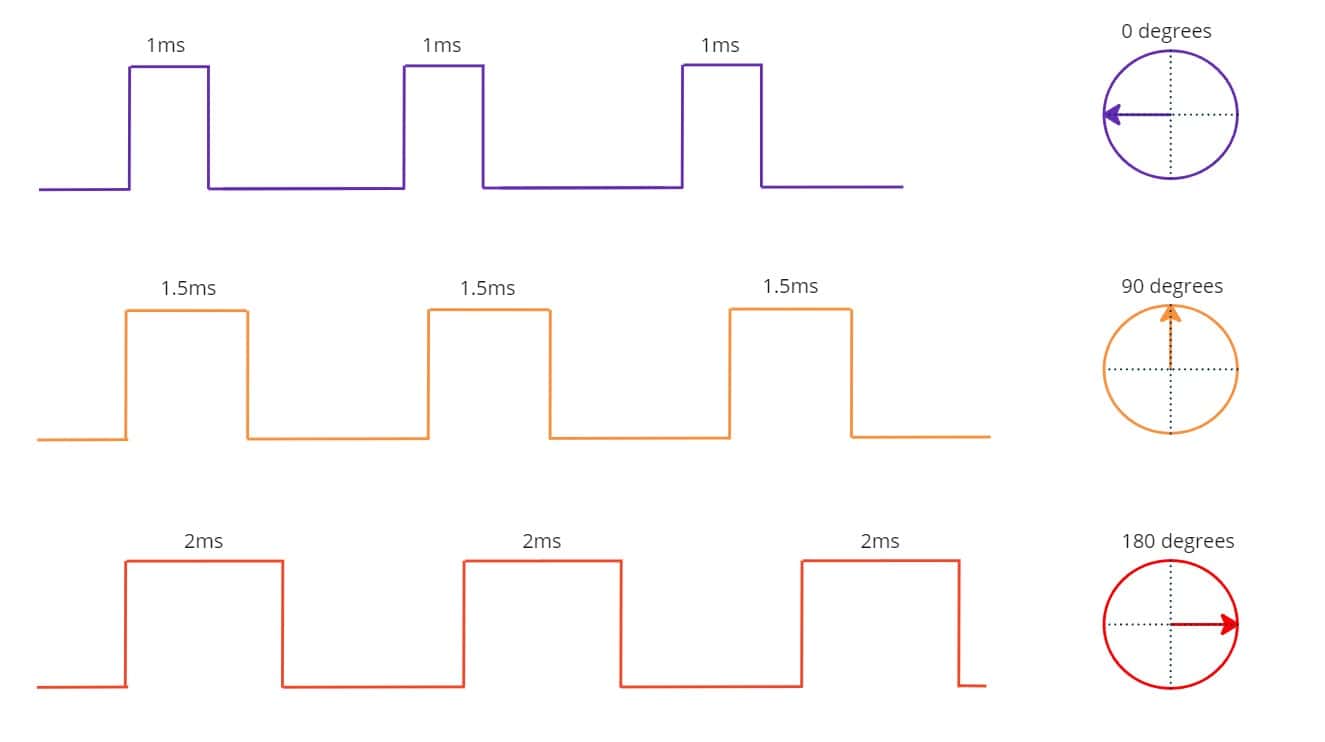
However, there is no standard rule that universally defines the relationship between pulse durations and servo positions. Different servos from various manufacturers can exhibit variations in their responses. Therefore, you may need to experiment and adjust the pulse durations to find the optimal position for your specific servo.
Even though Arduino is capable of producing PWM signals using analogWrite, there are not suitable for servos and may damage them. To avoid this, we can use the Servo library, which is already available in the Arduino IDE. This library enables us to control servo motors using Arduino very easily with minimal efford.
Attach a Servo to Arduino
Servos motors come with three wires:
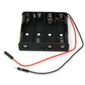
- Red – DC Voltage. Typically 5V – 6V. Connect to Arduino 5V or to an external power source.
- White/Orange – Signal. Connect to a PWM Arduino pin.
- Black/Brown – GND. Connect this to the Ground pin of Arduino.
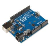
Below we show a basic wiring between a Servo Motor and Arduino.
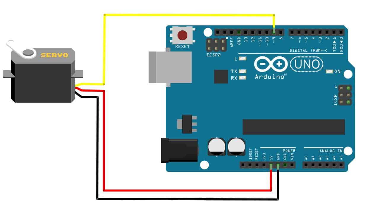
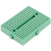
*For easier prototyping you can use a Breadboard.
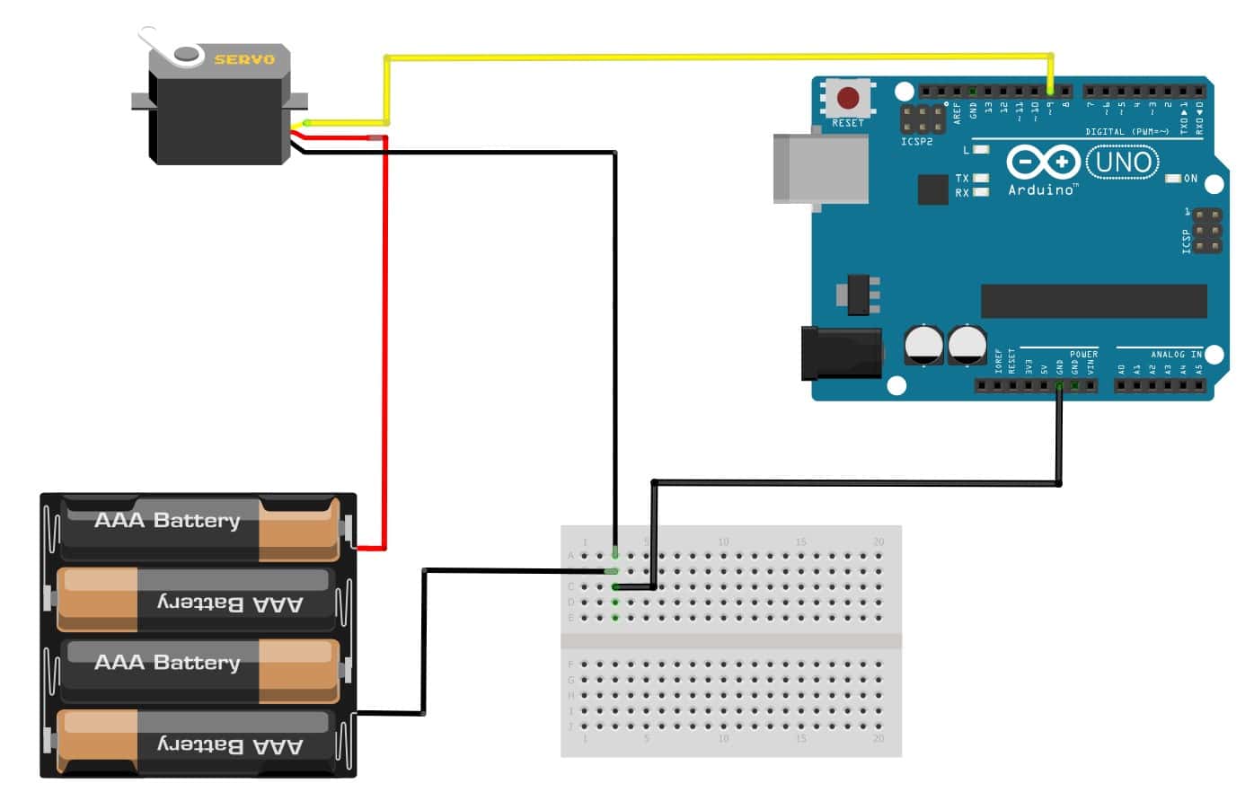
In general, it is advisable to use an external power source when working with motors and devices that require more power than the Arduino can provide. Without an external power source you risk to damage the Arduino board. However, the Ground of the Arduino and the external source must be connected.
After we complete the wiring, we move into writing code using the Arduino IDE. We make use of the Servo library that enables us to control servo motors with very little effort. Within the Arduino script, we declare a Servo object and call its attach method, specifying the pin number to which the signal wire of the servo is connected (In this case pin 9).
#include <Servo.h>

Servo servo;  // Create servo object to control a servo.

void setup() {
  servo.attach(9);  // Attaches the servo on pin 9 to the servo object.
}

void loop() {
  servo.write(90); // Write a value (between 0 and 180) to servo.
                   // This causes the servo to rotate.
}
Servo Library Calibration
As mentioned previously, due to the lack of a standard relationship between pulse durations and servo positions, it may be difficult to control the servo correctly and utilize its full range. If you have previously used a servo that wasn’t able to make a full 180-degrees rotation, there is a good change you need to calibrate the Servo library specifically for that servo.
By default, the Servo library has the lowest value of 544 microseconds for 0 degrees angle, and the highest value of 2400 microseconds for the 180 degrees. By setting the appropriate values to the Servo library we can utilize the full range of the servo.
The configuration is done by providing the appropriate values in the attach method of the Servo object:
#include <Servo.h>
Servo servo;

void setup()
{
   servo.attach(9, min, max); // Provide the appropriate min and max values.
}
Below, we present different servo models and their corresponding min and max values for the attach method:
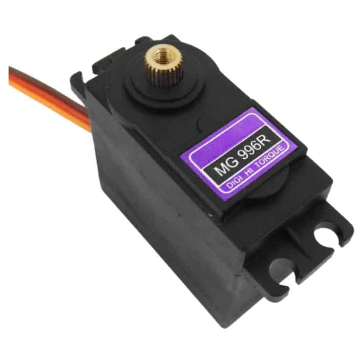
MG996R
Type: Angular
Min, Max: default

Traxxas 2055
Type: Angular
Min: 450
Max:2900
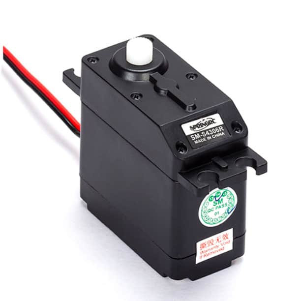
SM-S4306R
Type: Continuous Rotation
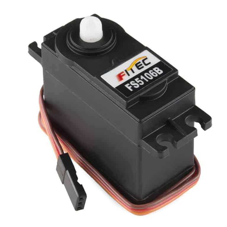
Fitec FS5106B
Type: Angular
Min: 680
Max: 2150
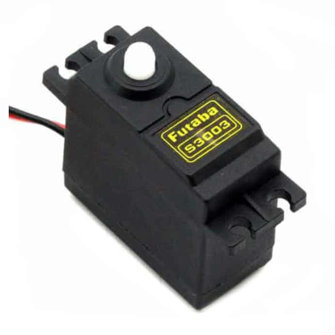
Futaba S3003
Type: Angular
Min, Max: default
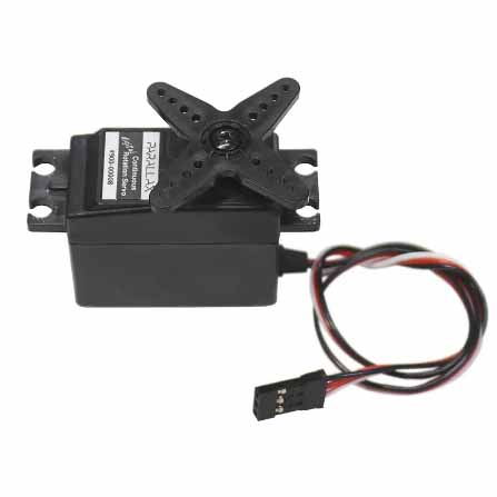
Parallax
Type: Continuous Rotation
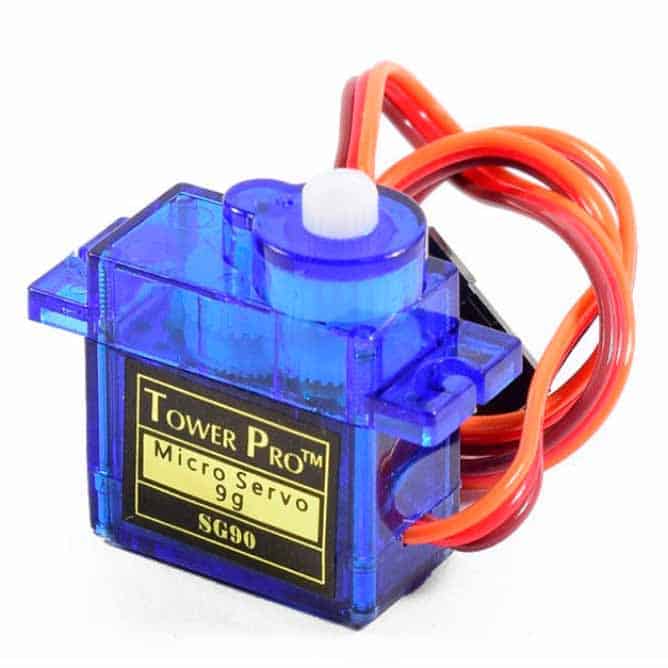
SG90 Micro
Type: Angular
Servo Sweep
This is a well known example, the ‘Hello World’ of servo motors, and you can find in the Arduino IDE. It applies for both angular and continuous rotation servo motors, but the results differ between the two.
The script writes all the values from 0 to 180 and then from 180 to 0, causing the servo motor to rotate clockwise and then in reverse, covering its full range. This process is repeated forever.
#include <Servo.h>

Servo myservo;  // create servo object to control a servo
// twelve servo objects can be created on most boards

int pos = 0;    // variable to store the servo position

void setup() {
  myservo.attach(9);  // attaches the servo on pin 9 to the servo object
}

void loop() {
  for (pos = 0; pos <= 180; pos += 1) { // goes from 0 degrees to 180 degrees
    // in steps of 1 degree
    myservo.write(pos);              // tell servo to go to position in variable 'pos'
    delay(15);                       // waits 15ms for the servo to reach the position
  }
  for (pos = 180; pos >= 0; pos -= 1) { // goes from 180 degrees to 0 degrees
    myservo.write(pos);              // tell servo to go to position in variable 'pos'
    delay(15);                       // waits 15ms for the servo to reach the position
  }
}
The 15ms delay allows the motor enough time to reach its target position.
Although you can run this example in both continuous rotation and angular servo motors, the result will be different. Below, we see in case of continuous rotations the speed and direction of the motor is changed, while for the angular servo motor the angular position is changed.
Servo oscillation
In this example, we make the servo motor oscillate between two positions that constantly increase.
Servo servo;

int _degrees[] = {30, 50, 60, 90};
int count;

void setup() {
  servo.attach(9, 500, 2900);  // Attaches the servo on pin 9 to the servo object.
  count = sizeof(_degrees) / sizeof(int); // Number of elements in the array.
}

void loop() {

  for (int i = 0; i < count; i += 1) {
    int left = 90 - _degrees[i];
    int right = 90 + _degrees[i];

    servo.write(left);
    delay(1000); // Wait for the servo to reach the position.
    servo.write(right);
    delay(1000); // Wait for the servo to reach the position.
  }
}
The above script creates oscillation in the servo motor by moving it back and forth between specified angles. This creates the movement pattern shown below:
Control Servo from Serial input
In this example, we control the rotation of the servo motor by providing the desired value in Serial using the Serial Monitor of the Arduino IDE.
#include <Servo.h>
Servo servo;
int pos = 0;

void setup()
{
   Serial.begin(9600);
   servo.attach(9);
}

void loop() {
   if (Serial.available())
   {
      int state = Serial.parseInt();

      if (state >= 1 && state <= 180)
      {
         Serial.println(state);
         servo.write(state);
      }
   }
}
The above script allows us to send angle values (ranging from 1 to 180) through the Serial Monitor. The servo will then move to the specified angle accordingly.
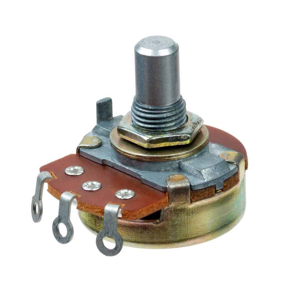
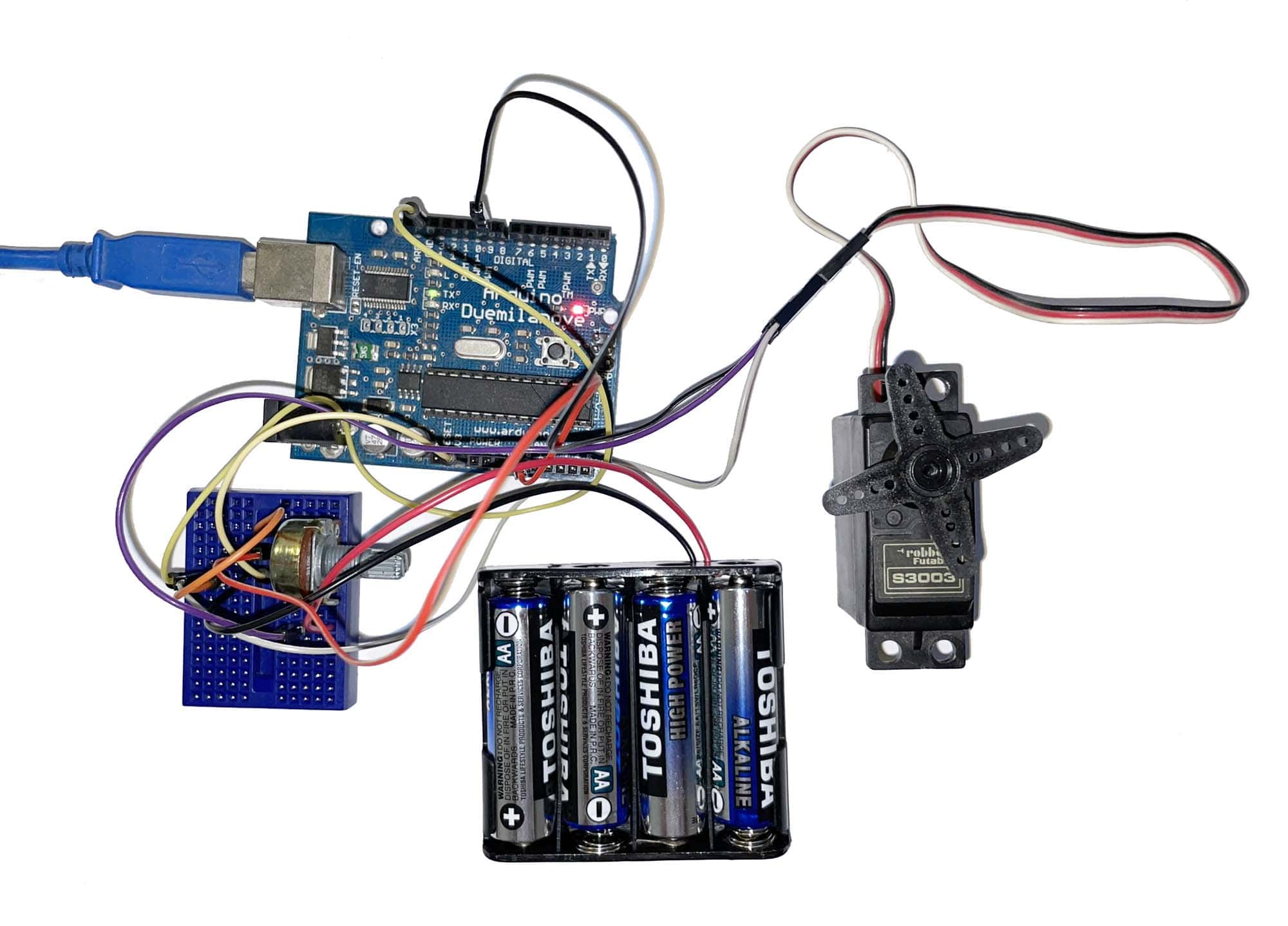
Control a Servo using a Potentiometer
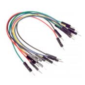
You can use a potentiometer to control the position of an angular servo motor, or the speed in case of continuous rotation servo motor. Potentiometers have three pins, one for Ground, one for Voltage and the last pin (usually the middle) is where the variable voltage is obtained and is connected to an analog Arduino input. We can read the output of the potentiometer, map it between the 0 – 180 range a servo can read (all analog reads in Arduino have a range from 0 to 1023) and then send the value to the servo motor.
#include <Servo.h>

Servo servo;

int potpin = 0; // The pin number which the potentiometer is attached.
int val; // Stores the value read from the analog pin.

void setup() {
  servo.attach(9);  // Attaches the servo on pin 9 to the servo object.
}

void loop() {
  val = analogRead(potpin); // Reads the value of the potentiometer (value between 0 and 1023).
  val = map(val, 0, 1023, 0, 180); // Scale the potentiometer value between 0 and 180.
  servo.write(val); // Writes the servo position according to the scaled value.
  delay(15);
}

The real circuit is shown below:
How to Control multiple Servo Motors with the same Arduino board
Typically, an Arduino board is capable of controlling up to 12 servos and the Arduino mega up to 48 using the Servo library. When dealing with multiple servos that may require more current than the Arduino can provide, an external power source should be added for the servo motors.
Control multiple Servos using Serial commands
In this example we show how we can control individual servos using user commands with a specific format.
#include <Servo.h>
#define SERVOS 4 // The number of servos.

int servoPins[SERVOS] = { 6,9,10,11 }; // Servo pins.
Servo myservo[SERVOS];

int pos = 0; // Store the servo position.

void setup()
{
  Serial.begin(9600);
  for(int i=0; i < SERVOS; i++)
    myservo[i].attach(servoPins[i]); // Attach each servo to its pin.
}

void loop()
{
  if ( Serial.available()) {
    char ch = Serial.read(); // Read a single character.

    if( isDigit(ch) ) // Check if ch is a number:
      pos = pos * 10 + ch - '0'; // Add current digit to previous one.
    else if(ch >= 'a' && ch <= 'a' + SERVOS) // Check if ch is a letter for our servos:
    {
      Serial.print("Write:");
      Serial.print(pos);
      Serial.print(" to servo:");
      Serial.println(ch);
      myservo[ch - 'a'].write(pos); // Write the position to the appropriate servo.
      pos = 0;
    }
  }
}
In the script above, we initialize the servos in the setup function using a for loop. We store their pin numbers in an array for easier access. Next, inside the loop method, we read a byte from Serial and if it is a digit we add it to the previous digit in order to form the whole number. If the byte is a letter between ‘a’ and ‘d’, we write the specified position to the corresponding servo. Notice that in C++ a character has an int representation. We can add an int with a character or compare them. This way the expression ‘a’ + SERVOS equals to ‘d’. Also the expression ch – ‘a’ (when we write the position to a servo) results in a number that corresponds to the correct index in the myservo array.
Below is the circuit diagram showing the four servos attached to the Arduino.